Arduino UNO Activity: An Application & Tutorial in Using Arduino to Eight LED Lights | Part 4 – “ How to Make a Traffic Light? Simulation Using 3 LED Lights (The Basics) “
Good day to all the readers! ^_^

INTRODUCTION
As you are on this article, I assume you already have an idea of what is this all about. If you don’t have any idea yet, however you are interested to gain some knowledge about this, then, I welcome you. I’m very glad to help you with that! I've been giving tutorials or activities involving Arduino/Arduino UNO. For the readers, especially the newbies, I recommend you to visit the given links below for some recapitulation:
Tutorial/Activity 1. Four LED Lights Off While the other Four LED Lights On
Tutorial/Activity 2. Continuous Turning On of Eight LED Lights, One By One - From LED 1 to LED 8
Tutorial/Activity 3. One by One Turning on of LED Lights... Ensuring That LED 1 to 8 Will Turn On BUT the Previous LED Lights Will Not Be Turned Off
On my previous posts, I already have explained the following terms. But for the purpose of reviewing these important terms, all you have to do is “ Just Click “ the Hyperlinked TERMS below:
For this new tutorial of mine, another feature of these open source software/hardware will be discussed. What is meant by another feature is another code, function and purpose. On this tutorial, the following codes will be discussed:
- const int (pushButton );
- buttonState
- digitalRead
- if…else
What is const?
The const keyword stands for constant. It is a variable qualifier that modifies the behavior of the variable, making a variable "read-only". This means that the variable can be used just as any other variable of its type, but its value cannot be changed. You will get a compiler error if you try to assign a value to a const variable.
Constants defined with the const keyword obey the rules of variable scoping that govern other variables. This, and the pitfalls of using #define, makes the const keyword a superior method for defining constants and is preferred over using #define.
What is Pushbutton?
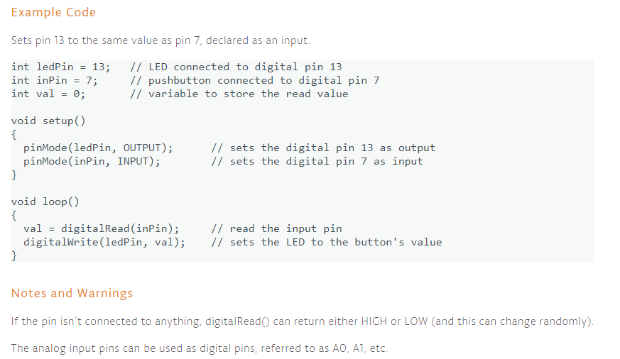
The pushbutton is a component that connects two points in a circuit when you press it. The example turns on an LED when you press the button.
We connect three wires to the Arduino board. The first goes from one leg of the pushbutton through a pull-up resistor (here 2.2 KOhms) to the 5 volt supply. The second goes from the corresponding leg of the pushbutton to ground. The third connects to a digital i/o pin (here pin 7) which reads the button's state.
When the pushbutton is open (unpressed) there is no connection between the two legs of the pushbutton, so the pin is connected to 5 volts (through the pull-up resistor) and we read a HIGH. When the button is closed (pressed), it makes a connection between its two legs, connecting the pin to ground, so that we read a LOW. (The pin is still connected to 5 volts, but the resistor in-between them means that the pin is "closer" to ground.)
What is buttonState?
Once you've got a pushbutton working, you often want to do some action based on how many times the button is pushed. To do this, you need to know when the button changes state from off to on, and count how many times this change of state happens. This is called state change detection or edge detection. In this tutorial we learn how to check the state change, we send a message to the Serial Monitor with the relevant information and we count four state changes to turn on and off an LED.
What is digitalRead?
Reads the value from a specified digital pin, either HIGH or LOW.
What is if…else?
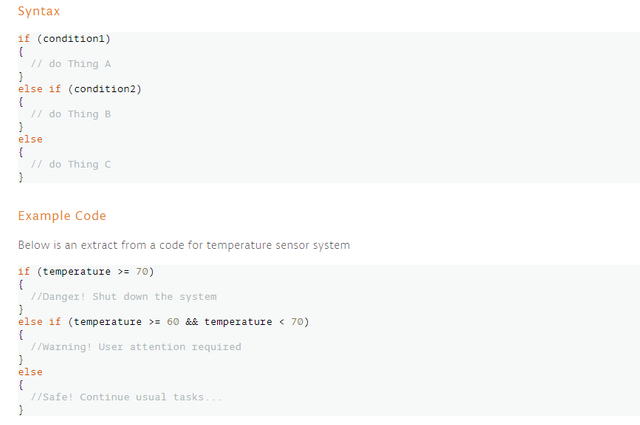
The if…else allows greater control over the flow of code than the basic if statement, by allowing multiple tests to be grouped together. An else clause (if at all exists) will be executed if the condition in the if statement results in false. The else can proceed another if test, so that multiple, mutually exclusive tests can be run at the same time.
Each test will proceed to the next one until a true test is encountered. When a true test is found, its associated block of code is run, and the program then skips to the line following the entire if/else construction. If no test proves to be true, the default else block is executed, if one is present, and sets the default behavior.
Note that an else if block may be used with or without a terminating else block and vice versa. An unlimited number of such else if branches is allowed.
To get a copy of the Arduino Software (IDE) just click here to download it.
Today is the fourth day in which I am able to use Arduino. Since then, for today, I will also be having my fourth tutorial on the said open source software/hardware. Now, on this tutorial you will gain knowledge on how those signaling devices positioned at road intersections, pedestrian crossings, and other locations to control the flows of traffic are being made, programmed and ran. Yes, I am referring to the Traffic Lights. For now, we will be doing the basics since this is just a tutorial.
Activity Name:
The Making Of A Traffic Light - Simulation Using 3 LED Lights Only (The Basics)
Materials and Equipment Used:
- Three Resistors (330 Ohms)
- One Breadboard
- Three LED Lights (Yellow, Red, Green)
- Connecting Wires
- Analog Multitester
- Arduino UNO with USB Cable
- Laptop with Arduino Application
- Push Button
Summarized Activity Instructions:
- Prepare the equipment needed for the activity.
- Use three (3) LED lights (Yellow, Red, Green) and three (3) resistors only for the activity. Use the Analog Multitester to test if the LED lights are operational. Operational LED lights will produce light when the terminals are connected properly.
- With the breadboard provided, make a circuit. In making the circuit, arrange the three LED Lights in this manner: Red, Yellow, Green. Remember that in every LED light, there must be a resistor connected to it. It is to reduce current flow, adjust signal levels, to divide voltages, bias active elements, and terminate transmission lines, among other uses. Also, since there is a Push Button involved for this activity, we must also connect a Push Button on the said circuit. Connect Arduino UNO and the made circuit on the breadboard using the connecting wires.
- Make a program of the activity using the Arduino Application on the laptop and verify if the created program is working or ready for uploading to Arduino UNO. Additional Information: Arduino Application has a verification/test button of the created program before running and using it to the circuit created in the breadboard. This is to make sure if the program works well to avoid errors or malfunctions of the system and for the safety of the programmer and the laptop that will be used.
- Now, connect the Arduino UNO which has been also connected to the made circuit on the breadboard to the laptop using the USB Cable.
- In the Arduino Application on the laptop, upload the created program to Arduino UNO and run the system.
- Once the program has been uploaded to the Arduino UNO, the circuit which has been connected to it (in the breadboard) will respond and perform the program uploaded.
Resulting Output
Once the Push Button on the circuit will be pressed, it will observed that the first LED light that produces light is the RED LED, followed by the YELLOW LED and then by the last LED light which is the GREEN LED.
Note: On the made program the following has been set.
- The delay of RED LED to YELLOW LED is 3 seconds.
- The delay of YELLOW LED to GREEN LED is 1 second.
- The delay of GREEN LED back to RED LED is 3 seconds.
What Resistor should I use? How many ohms and why?
The type of Resistor that will be used is a Linear Resistor having a value of 330 ohms. The reason why we will be using a 330 ohms resistor is because the amount of current and voltage that we will be producing is only small, about 5 volts only. The value of the said resistor will suffice the required amount of current and voltage on the circuit that will be made for the activity.
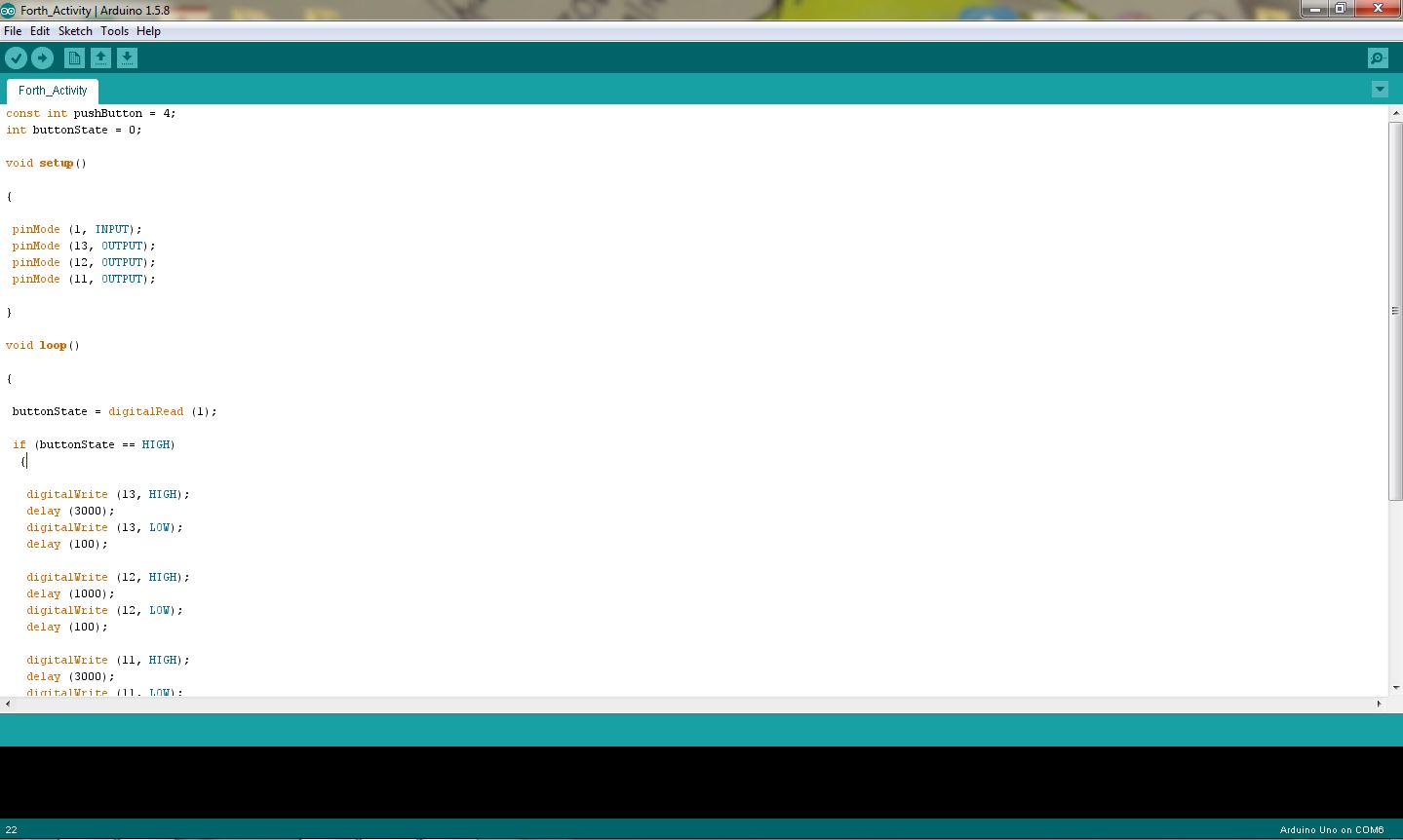
Activity Codes
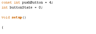
const int pushButton = 4;
int buttonState = 0;
void setup()
{
pinMode (1, INPUT);
pinMode (13, OUTPUT);
pinMode (12, OUTPUT);
pinMode (11, OUTPUT);
}
void loop()
{
buttonState = digitalRead (1);
if (buttonState == HIGH)
{
digitalWrite (13, HIGH);
delay (3000);
digitalWrite (13, LOW);
delay (100);
digitalWrite (12, HIGH);
delay (1000);
digitalWrite (12, LOW);
delay (100);
digitalWrite (11, HIGH);
delay (3000);
digitalWrite (11, LOW);
delay (100);
}
}
THE CODES AND THEIR MEANING
| pinMode (1, INPUT); | sets the digital pin 13 as input |
| pinMode (13, OUTPUT); | sets the digital pin 13 as output |
| pinMode (12, OUTPUT); | sets the digital pin 12 as output |
| pinMode (11, OUTPUT); | sets the digital pin 11 as output |
| digitalWrite (13, HIGH) ; | sets the digital pin 13 on |
| digitalWrite (12, HIGH) ; | sets the digital pin 12 on |
| digitalWrite (11, HIGH) ; | sets the digital pin 11 on |
| digitalWrite (13, LOW) ; | sets the digital pin 13 off |
| digitalWrite (12, LOW) ; | sets the digital pin 12 off |
| digitalWrite (11, LOW) ; | sets the digital pin 11 off |
| delay (3000); | waits for 3000 milliseconds or 3 seconds |
| delay (1000); | waits for 1000 milliseconds or 1 second |
| delay (100); | waits for 100 milliseconds or 0.1 second |
| const int pushButton = 4; | number of pushbutton 4 pin |
| int buttonState = 0; | set the default variable value for pushbutton status |
| buttonState = digitalRead (1); | read current states of the pushbutton value: |
VIDEO TUTORIAL (ON THE MAKING) - COMPLETE PROCESS
THE CIRCUIT
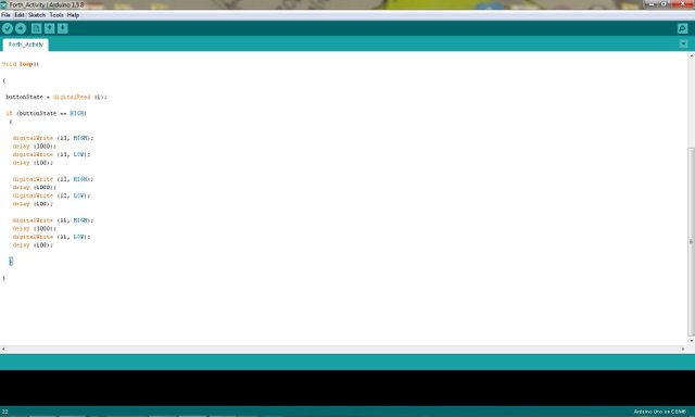
THE PROGRAM
Author: @rejzons
Posted on Utopian.io - Rewarding Open Source Contributors
Hey @rejzons I am @utopian-io. I have just upvoted you!
Achievements
Community-Driven Witness!
I am the first and only Steem Community-Driven Witness. Participate on Discord. Lets GROW TOGETHER!
Up-vote this comment to grow my power and help Open Source contributions like this one. Want to chat? Join me on Discord https://discord.gg/Pc8HG9x
thank you utopian-io
Thank you for the contribution. It has been approved.
You can contact us on Discord.
[utopian-moderator]
thank you sir @flauwy :)