Creating a water drop photograph timer - LCD, Menus and Buttons (Part 3)
Hey everyone,
The next stage of building the water drop timer is to add an LCD and menu system to enable me to easily adjust the timings for the system. Going to split this into three parts - LCD wiring, Button wiring and Menu Coding.
LCD wiring
The normal way of wiring up an LCD is something similar to what is shown in this link. The problem with this method is that it uses 6 output pins on the Arduino and that doesn't leave you with many spare. What you can do in this instance to reduce the amount of pins used to 3 is to use a 74HC595 shift register. I use these a lot to reduce the amount of pins used by the Arduino. They have 3 inputs and 8 or 16 outputs.
Think of the 8 outputs as 8 pipes that you fill with a ball using three commands, all should be filled before you can empty them. Command 1 holds the ball above the pipe ready to drop. Command 2 drops the ball into the pipe and then moves to the next pipe. Command 3 empties all of the pipes
So say you wanted to output 11000000 - you would issue a drop, a move, a drop and then 7 moves, followed by the pipe empty command. Simple eh?
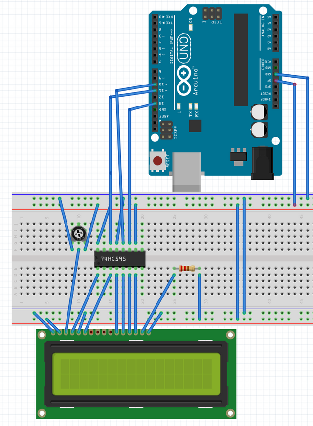
In the following schematic you can see the three connections coming from the Arduino and the 6 that come from the bottom side of the 74HC595 to the LCD display.
I'll try to give a brief overview of how an LCD display works. Of course, there are Arduino libraries that do the hard work for you but it's good to have some low level understanding for when things go wrong!!
From left to right on the LCD connections
First two pins are -ve and +ve to power the LCD driver.
Pin 3 is the contrast adjuster. You can see it is connected to a potentiometer which you can adjust to change the contrasts between text and backlight
Pin 4 is the Register Select pin. When this is HIGH the LCD knows you are sending data to it (ie, characters). When it is LOW, you are sending a command (ie, move the cursor to position 2x10 or clear the screen)
Pin 5 is the read or write pin. This is always set to write in this instance so is connected straight to GND
Pins 6-10 are unused as we are writing in 4 bit mode to the LCD
Pins 10-14 are the 4 bits that we use to send both commands and text to the LCD depending on the state of pin 4.
Pins 15 and 16 are power to the backlight
Full specs for the Hitachi HD44780 LCD are here
Of course, with an Arduino library you only have to do things such as
LCD.clear();
LCD.setCursor(0,0);
LCD.print("Hello World");
and the library does all the hard work of issuing command and converting the ascii text to binary for you.
Buttons
So onto buttons. Yet again you could end up with a problem of having multiple buttons using one input each on the Arduino. If you want to use 4 buttons to issue Up, Down, Select and Back commands, you don't really want to have to use 4 input pins on the Arduino for that. The best way around that is to use a single analog pin and somehow change the current that is going to that pin. The best way to do that is with a set of buttons, each one with a unique resistor value attached to it. Something like this....
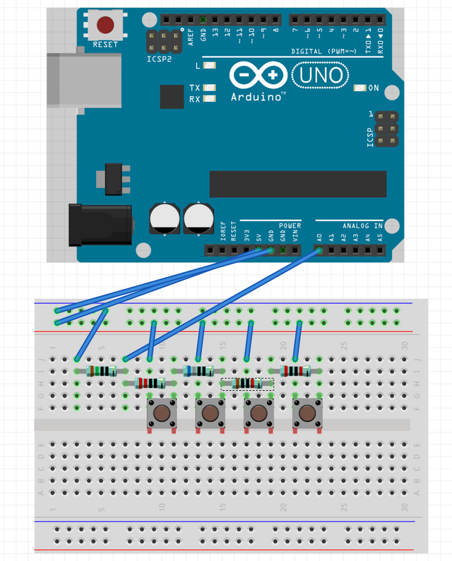
Looks a bit strange, but makes sense when you think about where the current flows. All the buttons are only connected on the top 2 pins. The first resistor on the left is just what is called a pull down resistor and prevents flaky readings on the A0 pin (analog input) when no buttons are pressed.
So imagine you press the first button on the left. That simply creates a circuit from live (the red line on the breadboard), through the button (which is now closing the circuit) through the resistor directly above the button and then back to A0. The value on A0 when this is pressed will be somewhere between 000 and 1000 (in terms of what the Arduino reports in the code), preferably as high as we can get as it has the least resistance of all the buttons (as you will see shortly).
Moving onto the second button. On pressing this the circuit is created from live, through the button, through the resistor above the button but also then through the first buttons resistor on its way back to A0. Going through two resistors reduces the current further and therefore the value that appears on A0 has a lower value in the code. This gives all 4 buttons distinct values on A0 when they are pressed - the resistance increases as you move along the row of buttons. If you are really clever and use the right resistors, you can end up with values where you can determine which combination of buttons are pressed at the same time.
If you check the values coming into the A0 pin in the Arduino serial monitor you can then see where the levels are. For example, for my setup I get the following
const int BUTTON1 = 1; // 835
const int BUTTON2 = 2; // 530
const int BUTTON3 = 3; // 244
const int BUTTON4 = 4; // 72
the values will vary ever so slightly due to tolerances on resistance, heat etc. For this reason, in the code I check between high and low values that cover the range of values i expect
const int BUTTON1LOW = 800;
const int BUTTON1HIGH = 900;
const int BUTTON2LOW = 500;
const int BUTTON2HIGH = 600;
const int BUTTON3LOW = 200;
const int BUTTON3HIGH = 300;
const int BUTTON4LOW = 50;
const int BUTTON4HIGH = 100;
So here is a quick video of the buttons and LCD in action. Behind the scenes there is code that manages the menu system which i'll briefly go into in a moment.
Menu Coding
I am not going to post reams and reams of code here. The full codebase will be published on github when the project is completed. I just wanted to go through some basic pseudocode and details of what libraries I have used.
For the menu system I have changed the code from MenuBackend so that every menu item has a corresponding DataObject which stores the actual value associated with the MenuItem. The MenuBackend library has no concept of menu items having numeric, changeable values and of course, this was imperative in this project.
Setting up menus is pretty easy; you just create MenuItem objects and add them to each other.
For example
DataObject dropTimeMs = DataObject("Drop Time ms", 1000, 10, 10);
DataObject shutterDelayMs = DataObject("Shutter Delay", 500, 10, 20);
DataObject shutterOpenMs = DataObject("Shutter Open Time ", 2500, 10, 30);
DataObject flashDelayMs = DataObject("Flash Delay", 1000, 5, 40);
DataObject flashSwitchTimeMs = DataObject("Flash Switch Time", 500, 10, 50);

menuSubItem1 =  MenuItem(dropTimeMs, Serial);
menuSubItem2 = MenuItem(shutterDelayMs, Serial);
menuSubItem3 = MenuItem(shutterOpenMs, Serial);
menuSubItem4 = MenuItem(flashDelayMs, Serial);
menuSubItem5 = MenuItem(flashSwitchTimeMs, Serial);

menu.getRoot().add(menuSubItem1).addRight(menuSubItem2).addRight(menuSubItem3).addRight(menuSubItem4).addRight(menuSubItem5);
Then you call methods like moveRight(), moveLeft() to navigate. The functionality I added was to include an editing mode. When you hit the select button on an item that has no child item, you enter editing mode. The data object associated at that level has a min value, max value, increment amount and where the value is stored in the EEPROM of the Arduino. The EEPROM is a persistent store so that you don't lose the values you have set between uses.
In terms of what the main program loop in the Arduino does, it's real basic.
void loop() {
   readMenuButtonInput(); // gets the current button input and stores it globally
   navigateMenus(); // acts on the button input
}
There is a 'debounce' delay to ensure that if the button is held down, the menus don't go crazy. Input is only taken once the button has been released before it it pressed or if the button has been held down for one second.
That pretty much sums up progress so far. Im just waiting on some spade terminal connections to connect my solenoid up to the circuit with. Some plastic tubing turned up today so I need to go into detail on how to set up a mariotte syphon to ensure consistency of pressure through the dripping system. I have the flash and camera connected up and working so once those things are here, I should be pretty close to setting up a working prototype.
Thanks for reading, hope you enjoyed it.
Mark
This post has been voted on by the SteemSTEM curation team and voting trail in collaboration with @utopian-io and @curie.
If you appreciate the work we are doing then consider voting all three projects for witness by selecting stem.witness, utopian-io and curie!
For additional information please join us on the SteemSTEM discord and to get to know the rest of the community!
Congratulations @markangeltrueman! You have completed the following achievement on the Steem blockchain and have been rewarded with new badge(s) :
Click here to view your Board of Honor
If you no longer want to receive notifications, reply to this comment with the word
STOPDo not miss the last post from @steemitboard:
Hi @markangeltrueman!
Your post was upvoted by Utopian.io in cooperation with @steemstem - supporting knowledge, innovation and technological advancement on the Steem Blockchain.
Contribute to Open Source with utopian.io
Learn how to contribute on our website and join the new open source economy.
Want to chat? Join the Utopian Community on Discord https://discord.gg/h52nFrV
Me and my dutch friend used to do arduino. that was maybe 3 yrs ago. nice post :)
Congratulations @markangeltrueman! You have completed the following achievement on the Steem blockchain and have been rewarded with new badge(s) :
Click here to view your Board of Honor
If you no longer want to receive notifications, reply to this comment with the word
STOPDo not miss the last post from @steemitboard: