Simulating 3-phase Y-Y balanced circuit using Multisim (with steps provided) with MATLAB
Simulating circuits in a software may not as bad as you think. It is a great tool for checking before an actual application and to visualize how the circuit itself works.
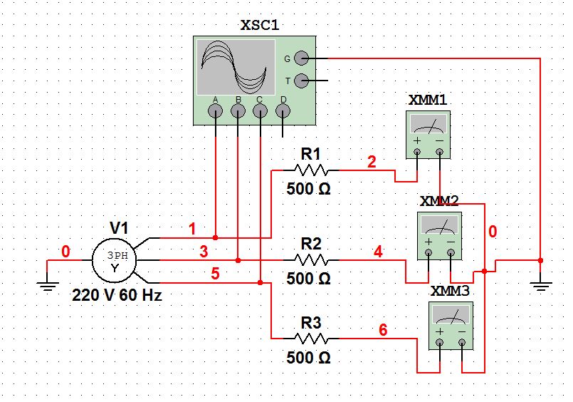
As the illustration above indicated, We are simulating a purely resistive load without a capacitor or an inductor. Using a Three-phase voltage wye source of 220Vrms (phase) and a resistor of 500 ohms. We will now solve the line currents Ia, Ib and Ic using a Digital Multitester and an oscilloscope to watch our 3 phase sinusoidal waveform.

First open the Multisim and open a new worksheet.
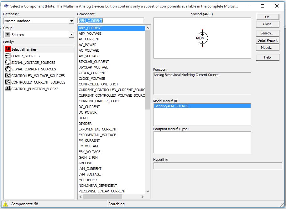
After clicking the component's tool. Find the THREE_PHASE_WYE and RESISTOR_RATED for your source and load.
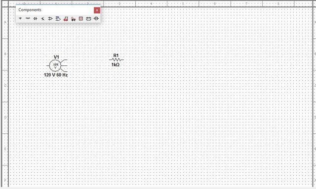
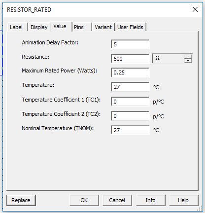
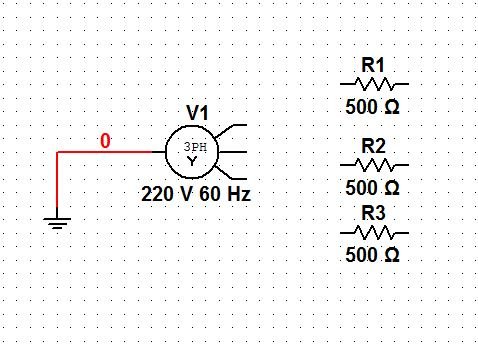
Now, double click at the resistor and change it to our desired ohmic value which is 500. And our source at 220 volts , 60Hz
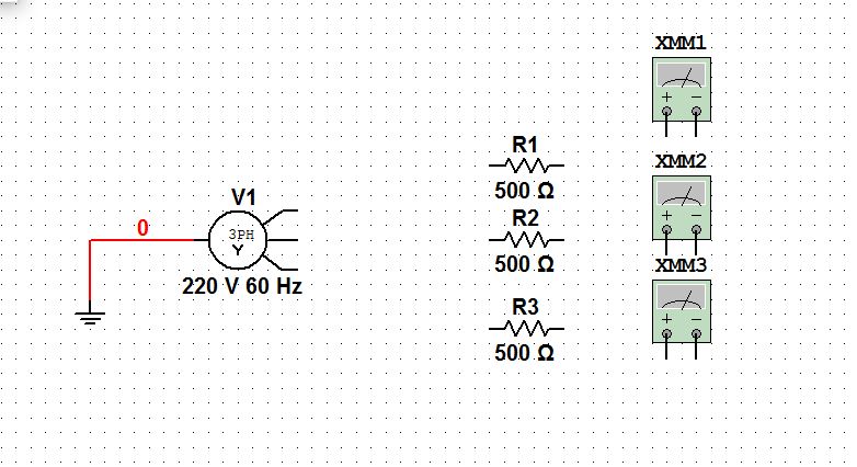
Then find the intrument's palette which is located at the right side (default set-up). And click the Multimeter. Get three and put them adjacent to the loads to measure the line currents going away from the load.
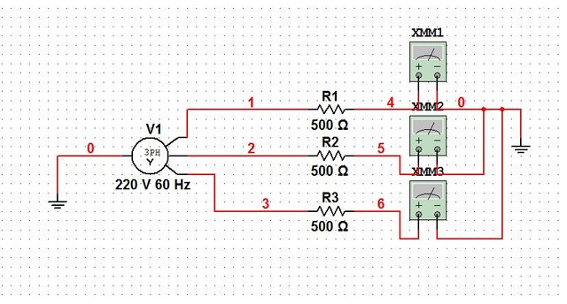
Connect it terminal by terminal (make sure it is properly connected insuring that there's a big red dot to each nodes). And get a Ground from the compoments and place it to another terminal of your tester.
note: the circuit will not run without a ground.
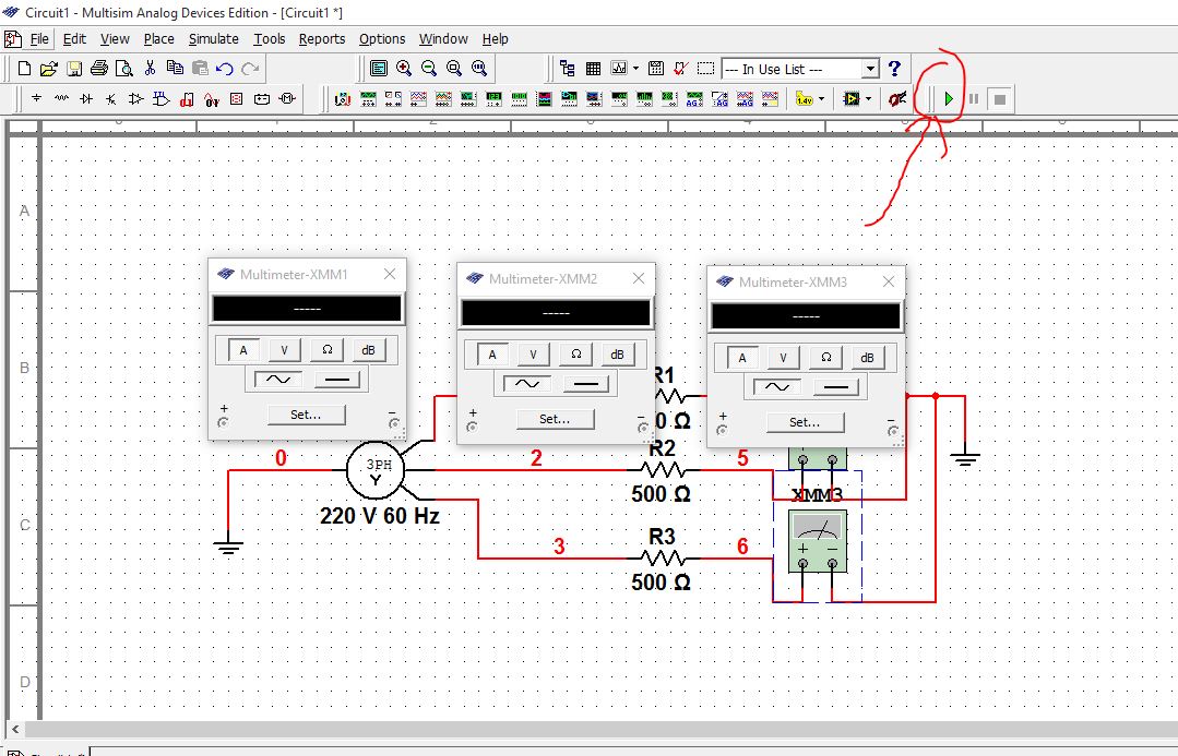
Now, Click each of the tester and an indicator pops up. Then, click the A and the AC button for measuring current in amperes and It is in AC.
And start the simulation by clicking the green triangular button.
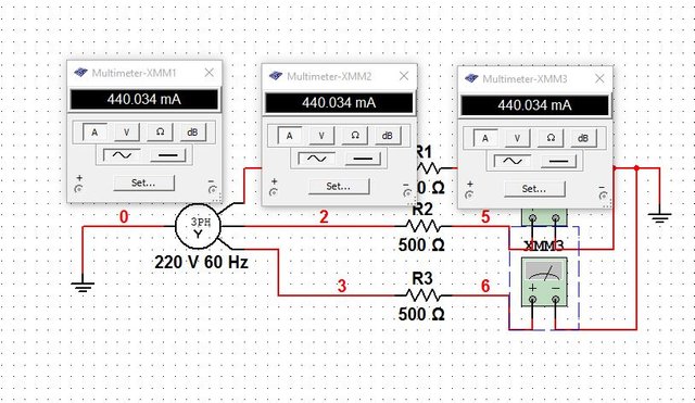
There you have it, The three currents measuring 440.034 milliamperes respectively, since we are having a balanced load.
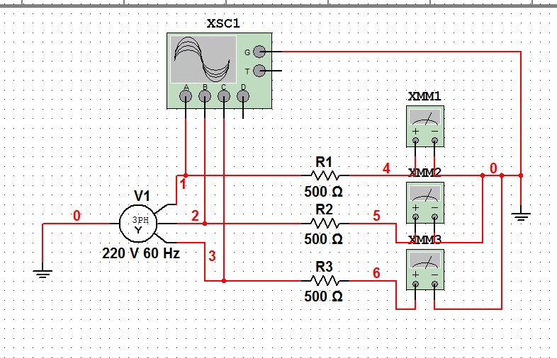
From the instuments find the four channel oscilloscope and place each of the terminals to:
channel A to line 1
channel B to line 2
channel C to line 3
ground to ground
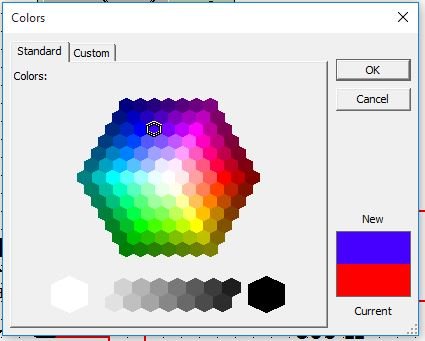
You can change the wire's connection color so you can indicate the phase difference of each channel.
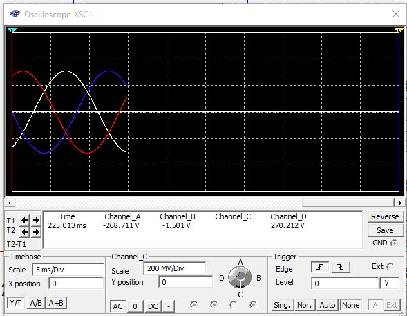
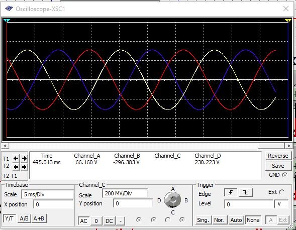
And now you have the nice 120 degree difference of a three phase Alternating Current source.
*As simulating the circuit above the resistor may pop up because it cannot hold such amount of power from the source. you can change the MAXIMUM RATED POWER (WATTS) higher than 0.25.
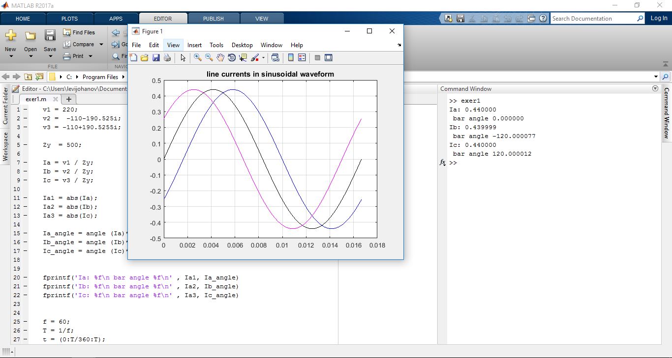
For the next post, I will have a step by step tutorial of MATLAB simulation of this circuit as shown below.
THANK YOU FOR READING, I HOPE YOU ALL LEARN A LOT :)
your's truly @leviticusjohan