Arduino Blog no.12 How to make a progress bar using Oled Display and Rotary encoder
Repository:
https://github.com/arduino/Arduino
What is Arduino?
Arduino is an open source electronics platform accompanied with a hardware and software to work on, develop and test complex electronics prototypes and products which is preferred in any way possible for students, hackers ,newbies, makers and hobbyists. Everyone can give life to electronic gadgets on their own do it your self projects. building own creative toys, a weather station, mini arcade games, play music, make an Led blinking chaser which involved hard electronics and software skills. Arduino helps us to understand the concepts of electronics and develop the software.
What Will I Learn?
In This tutorial you will learn the following.
- You will learn The basic basic programming skill of arduino
- You will learn on how to connect electronic modules to arduino
- You will learn how to display text and progress loader to OlED display
Requirements
For this part we need these following arduino components.
- OLED Display
- Arduino Microcontroller board
- Jumper wires
- Breadboard
- Rotary encoder
Difficulty
- Basic
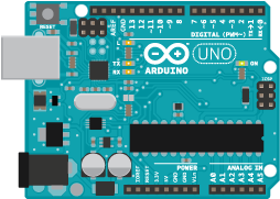
The Uno is a great choice for your first Arduino. It’s got everything you need to get started, and nothing you don’t. It has 14 digital input/output pins (of which 6 can be used as PWM outputs), 6 analog inputs, a USB connection, a power jack, a reset button and more. It contains everything needed to support the microcontroller; simply connect it to a computer with a USB cable or power it with a AC-to-DC adapter or battery to get started. reference
Tutorial Contents
This tutorial contains the following:
- Introduction of arduino software IDE
- INCLUDE Adafruit-SSD1331 Library to IDE
- Build the code| Declare and include function of the sketch
- Initialization of SETUP and LOOP() Function
- Building the Circuit
Arduino IDE is the open source software to write sketch code and upload it to the Arduino microcontroller board. Arduino IDE runs on Windows, Mac OS X, and Linux. The environment is written in Java and based on Processing and other open-source software. We can choose between the Installer Windows (.exe) and the Zip packages. Arduino suggests us to use the first one that installs directly everything you need to use the Arduino Software (IDE), including the drivers. With the Zip package you need to install the drivers manually. The Zip file is also useful if you want to create a portable installation. reference to arduino mainpage
- Dowload the arduino Desktop IDE: https://www.arduino.cc/en/Main/Software
When the download is finished, un-zip it and open up the Arduino folder to confirm that click yes, there are some files and sub-folders inside. The file structure is important so don’t be moving any files around unless you really know what you’re doing.
- We can power and program the colored oled display using SSD1306 library by adafruit Download the .ZIP library here: https://github.com/adafruit/Adafruit_SSD1306
INCLUDE Adafruit-SSD1306 Library to IDE
Arduino suggests us to use the 2 procedures on how to add libraries to the IDE but for this post i will be using the manual setup. Add zip file library. these process needs a couples of clicks or we can called it the manual mode. once we have downloaded the zip library. Launch the Arduino IDE then navigate to "SKETCH" > "INCLUDE LIBRARY"> add ZIP library then locate the downloaded library in your DOWNLOADS Folder, Arduino uses libraries to program electronic devices easily.The predefined libraries are written in C and C++ language, One can even write his software in C\C++ and use them on Wiring boards. While sketching hardware we need to call the predefined functions and rest will be handled by the Wiring software.
INCLUDE/SET the variables, libraries, oled address .etc
#include <Wire.h>
#include <Adafruit_GFX.h>
#include <Adafruit_SSD1306.h>
// If using software SPI (the default case):
#define OLED_MOSI   9
#define OLED_CLK   10
#define OLED_DC    11
#define OLED_CS    12
#define OLED_RESET 13
Adafruit_SSD1306 display(OLED_MOSI, OLED_CLK, OLED_DC, OLED_RESET, OLED_CS);
int val=-1;
int encoder0PinA = 3;
int encoder0PinB = 4;
int encoder0Pos = 0;
int encoder0PinALast = LOW;
int n = LOW;
int maxValue = 10;INITIALIZE The SETUP Functions
void setup() {
  pinMode (encoder0PinA, INPUT);
  pinMode (encoder0PinB, INPUT);
  display.begin(SSD1306_SWITCHCAPVCC, 0x3C);  // initialize with the I2C addr 0x3D (for the 128x64)
  Serial.begin (9600);
}INITIALIZE The LOOP() Functions
void loop() // this function runs over and over again
 {
  n = digitalRead(encoder0PinA); //read the encoder0PinA and store the state in a variable.
  if ((encoder0PinALast == LOW) && (n == HIGH)) {
    if (digitalRead(encoder0PinB) == LOW) {
       if( encoder0Pos > 0 ){
           encoder0Pos--;
       }
    } else // otherwise
*/
Declare encoder0PinA set to fron LOW to HIGH value, rotating the encoder to right it will increase the value set to 100%, set encoder0PinB from LOW, rotate the encoder to left will decrease its value
/*
{
      if( encoder0Pos < maxValue ){
          encoder0Pos++;
      }
    }
    Serial.print (encoder0Pos);
    Serial.println();
  }
  encoder0PinALast = n;
if( val != encoder0Pos ){
    val = encoder0Pos;
   display.clearDisplay();
   display.setTextSize(2); // set font size to 2 you can set it up to 3
   display.setCursor(0,1);
   display.setTextColor(WHITE);
   display.print("VOL:"); // set the word VOL to be display on the oled
   display.print(encoder0Pos * 10);
   drawProgressbar(0,20,120,10, encoder0Pos * 10 ); // declare the graphics fillrect(int x, int y, int width, int height)
   display.display();
}
}
void drawProgressbar(int x,int y, int width,int height, int progress)
{
   progress = progress > 100 ? 100 : progress; // set the progress value to 100
   progress = progress < 0 ? 0 :progress; // start the counting to 0-100
   float bar = ((float)(width-1) / 100) * progress;
   display.drawRect(x, y, width, height, WHITE);
   display.fillRect(x+2, y+2, bar , height-4, WHITE); // initailize the graphics fillRect(int x, int y, int width, int height)
  }
}The Connection of OLED and Rotary to Arduino R3 Board
Below is the connection diagram show how wiring should be done based on the code selected output pin of the OLED to arduino.The input pin of rotary encoder interrupt is PIN 3 of Arduino Uno, while PIN 4 is only used as a regular input, were not going to use SW pin since its not needed necessarily in this post. (SW pin is button of rotary encoder when pressed)
// If using software SPI (the default case):
#define OLED_MOSI   9
#define OLED_CLK   10
#define OLED_DC    11
#define OLED_CS    12
#define OLED_RESET 13
Proof of work
Here is the result of this activity, you copy the enrtire sketch code from the on my repository:
https://github.com/lapilipinas/Arduino-progressBAR-OLEDandRotaryEncoder
Conclusion
I have created one tutorial about color oled yesterday that was my blog no 11. all in all I don't experience any faulty message from the IDE while compiling, Thanks to adafruit for making a lot more easier for us to make a code. I am still on a testing state of arduino components in making a code, The main purpose of this project you can built a volume meter display, you can add more components like speaker or an mp3 module and more, depends on your desire project. There would be a percentage (%) on the progress, beacause the size of the oled is too small, i just remove it since there is the number of VOL so it's not needed if necessary.
Useful links and references
Arduino Main Website
: https://www.arduino.ccSSD1306 oled driver library for 'monochrome' 128x64 and 128x32 OLEDs
: https://github.com/adafruit/Adafruit_SSD1306Diagram Created using Fritzing
: http://fritzing.org/download/Screenshots edited using MS paint and blog created using BUSY
: https://busy.org/Learn more about arduino and it's electronic modules
: https://www.sparkfun.com/