Creating an IC type 7493 ripple counter component in BOOLR

Intended Learning Outcome (What Will I Learn?)
After reading and participating in this tutorial, the readers should be able to:
- create a new custom component for an IC type 7493 ripple counter ; and,
- simulate the operation of 7493 IC ripple counter.
Requirements
To be able to follow this tutorial, you should have the following tools at hand:
- A desktop PC or laptop with Windows (7, 8, 10) operating system; and,
- A BOOLR latest release version which you can download at its Github repository GGBRW/BOOLR or vist its website at boolr.me
Difficulty
- Intermediate
Tutorial Content
In today's discussion, we will talk about creating a custom component in BOOLR logic simulator. We will build by following the standard logic design for an IC type 7493 ripple. After creating the IC type 7493 ripple counter component in BOOLR, we will use it on a circuit; and, simulate its operation. Basically, a 7493 IC is a 4 bit ripple counter build around 4 cascaded JK Flip-flops. It has 4 sets of inputs(A,B, R1, R2) and outputs ( QA,QB,QC,QD).
Part 1: Configuring and creating JK flip-flop component
We will start by creating a custom component for JK Flip-flop. The JK flip-flop is constructed with two cross-coupled NOR gates and two AND gates. By the way, a JK flip-flop is a refined RS flip-flop where RS has an indeterminate state defined by J and K.
The input J and K is connected to one terminal in each AND gates. A clock added as a set of input that will enable the state of the input J and K. The indeterminate states in a flip-flop is carried out by connecting the output terminal of one NOR to another, and vice versa. In addition, the indeterminate state og input J and K are set by connecting the input state.
To begin configuring the JK flip-flop, open a new board in the BOOLR simulator. Then select and connect each components as defined above. ( You can read my other tutorial on how to do basic operations such as connecting and selecting components from my first tutorial:introduction to BOOLR.)
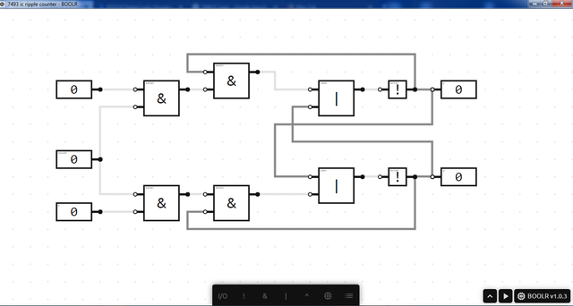
After constructing the circuit, we need to properly define the the input and output labels. This labels will be the new terminal designation that will appear in the custom component that will be creating. To edit component properties, right click the component and select EDIT.
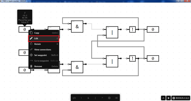
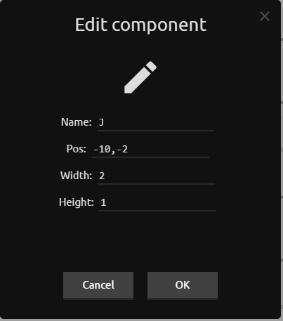
Define all input and ouput labels as J, K and CP for inputs; and Q and Q' for the ouputs.
Now, we will integrate the JK Flip-Flop logic circuit as one component named as JK FLIP-FLOP. First is select all components in the circuit by pressing SHIFT + RIGHT CLICK + DRAG/SELECT.
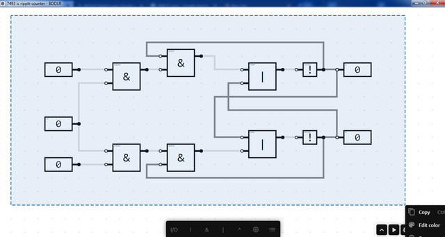
Next, you are give four options/actions to be done. Select componentized to merge all selected component into one custom component.
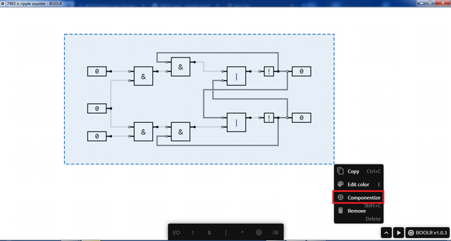
After, you will have a custom component with equal set of input and output. Double click this component and you will be directed to the custom component editor.
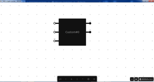
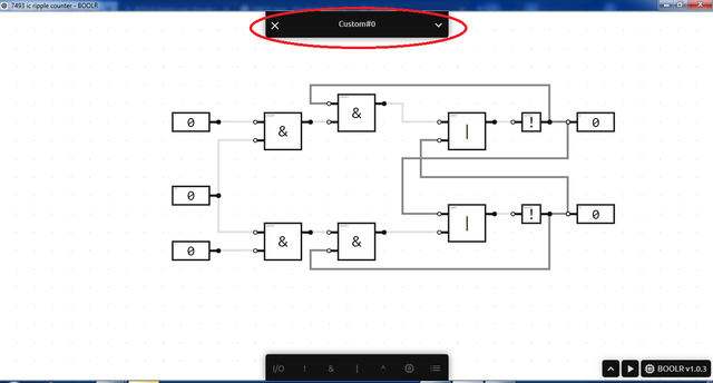
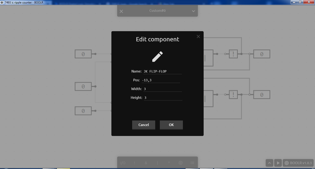
Now, we rename the new component as JK FLIPFLOP by clicking on the drop down menu at the custom#0 header. After, save and close the custom component editor.
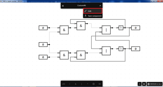
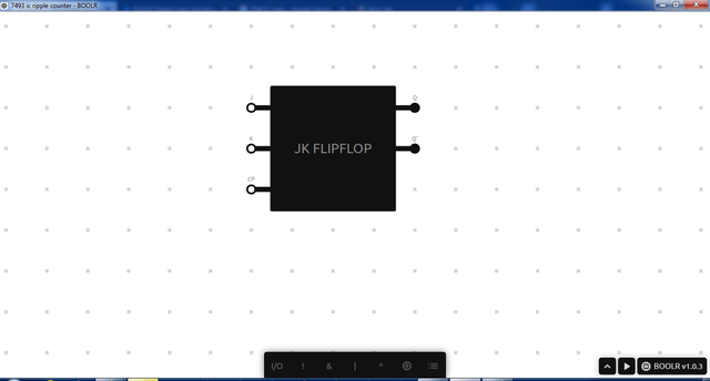
This is now the final look of the new nested JK flip-flop component.
**Part 2: Creating the custom component 7493 IC ripple counter **
The 7493 IC is a 4-bit ripple counter or an asynchronous counter where only the first flip-flop is clocked by an external clock. All subsequent flip-flops are clocked by the preceding flip-flop's ouput. It has 4 sets of inputs and outputs by which input are either a logical decimal or BCD. At the output, it is expected to have an incremented by one from the previous output, regardless of the input values. Now, let start creating the custom component for the 7493 IC ripple counter.
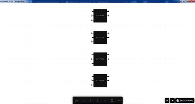
Start by creating 3 duplicates of the newly configure JK flip-flop component. Make sure to arrange it vertically with proper spacing.
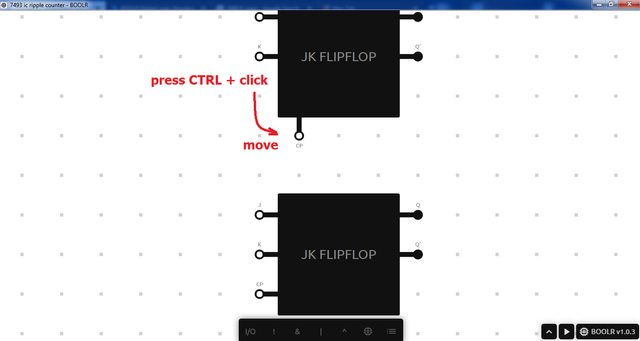
Move the CP terminal directly below the component box. Do it by holding the CTRL key and clicking on terminal then move.
Add 4 sets of input and output where two of the input is directly feed to an NAND gate.
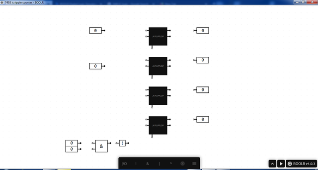
Connect the circuit accordingly and change input and output labels as A,B, R1, R2 for the input and QA,QB,QC,QD for the ouput
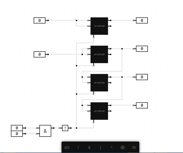
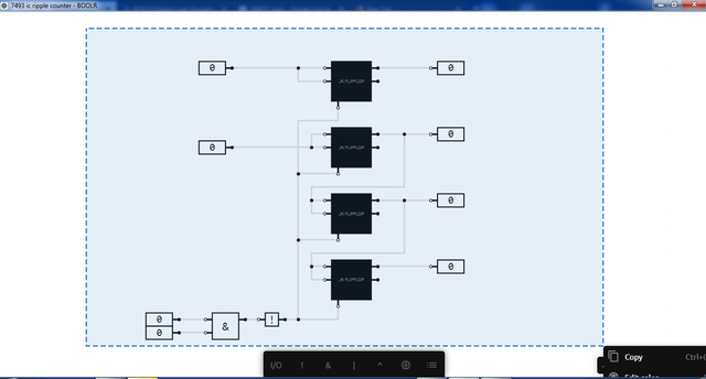
Merge the constructed circuit by selecting all components. Do it by holding the SHIFT key + SELECT components. To finalize the merging, select componentized.
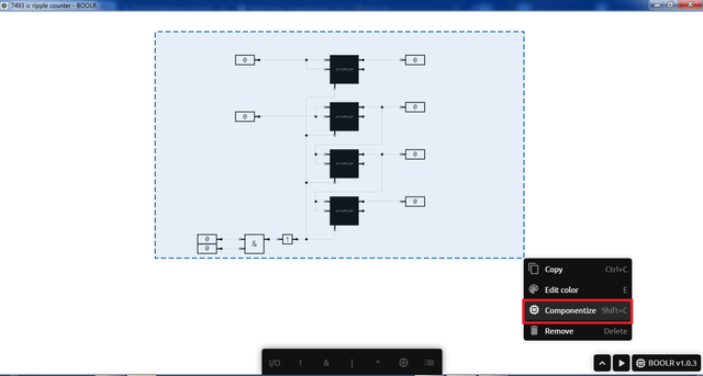
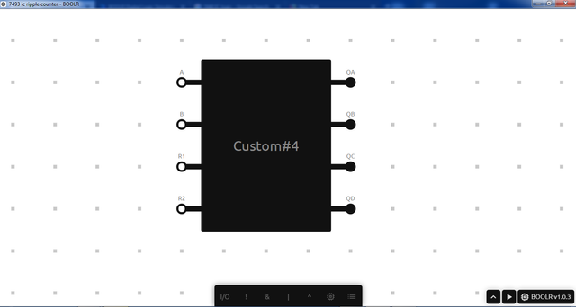
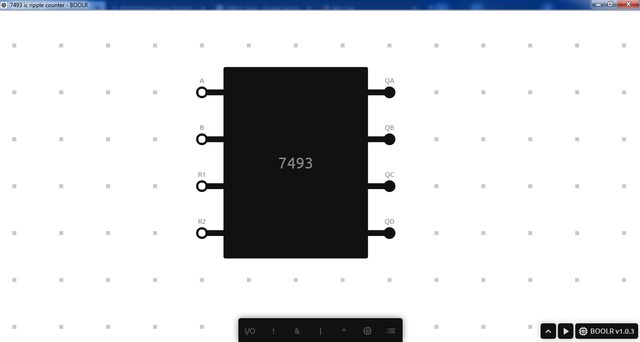
Now, change the nested component name form custom #0 to 7493. This is to represent the 7493 IC ripple counter.
** Part 3: Simulation.**
To test if the created nested component for 7493 IC ripple counter, connect input and output component to the 7493 IC then simulate.
Curriculum
You can browse the other curriculum for BOOBLR Digital Logic Simulator.
- Introduction to BOOLR Digital Logic Simulation
- Half Adder
- Half Subtractor
- Exclusive-OR implemented with AND-NOT-OR gates
- Flip-Flop
Posted on Utopian.io - Rewarding Open Source Contributors
Thank you for the contribution. It has been approved.
You can contact us on Discord.
[utopian-moderator]
Thank you @kizilelma
Hey @juecoree I am @utopian-io. I have just upvoted you!
Achievements
Suggestions
Get Noticed!
Community-Driven Witness!
I am the first and only Steem Community-Driven Witness. Participate on Discord. Lets GROW TOGETHER!
Up-vote this comment to grow my power and help Open Source contributions like this one. Want to chat? Join me on Discord https://discord.gg/Pc8HG9x