BOOLR Digital Logic Simulator | [3] Full Adder logic circuit simulation.
What is FULL ADDER?
| Full Adder is a combination circuit that forms the arithmetic sum of three input bits. It consists of three inputs and two outputs. Two of the input variables, denoted by x and y, represent the two significant bits to be added. |
|---|
Intended Learning Outcome (What Will I Learn?)
After reading and participating in this tutorial, the readers should be able to:
- learn basic basic logical function of Full Adder using simulation;
- create a digital logic circuit for Full Adder simulation ; and,
- simulate the created Full Adder simulation digital logic circuit.
Requirements
To be able to follow this tutorial, you should have the following tools at hand:
- A desktop PC or laptop with Windows (7, 8, 10) operating system; and,
- A BOOLR latest release version which you can download at its Github repository GGBRW/BOOLR or vist its website at boolr.me
Difficulty
- Intermediate
Part 1: Setting up a new project the BOOLR app.
1 | Open BOOLR.exe from the downloaded latest release zip file of the app.

2 | Create a new project by clicking NEW BOARD.

Then, you will be directed to Create New Board where you are ask to type in the name of the new board.

Type in the board name. For this tutorial, lets have "Full Adder" as board name.

3 | Click  to finalize setting up a new project.

| For the basic operations and functions of the BOOLR Digital Logic Simulation, you are advise to read Introduction. |
|---|
Part 2: Creating a Full Adder Digital Logic Circuit in BOOLR
Now, we create a circuit in the BOOLR. For this tutorial, we will create a cascaded circuit of two Half Adder. You may read my last tutorial about Half Adder.

1 | We start by creating Half Adder, Similar to what is shown above. Add the XOR gate in the worksheet, simply click at where you want the to add the component.

2 | Add AND gate by clicking  and following the process mentioned in step 2. Place it below the XOR gate. Make sure that the not gate is not connected to the output of the XOR gate.

4 | Select input devices from  . From the menu click on INPUT.

5 | Add three set of input on the left of the XOR gate but not directly connected to. Follow what is shown below.

6 | Add an OR gate to the outputs of the to adder.
Discussion: An OR gates has two input lines and one output line. Basically, as long as the inputs are a 1, the resulting output value is a 1. Note in the truth table, the only time the output is 0 is when both inputs are 0. You can browse the the OR truth table by right clicking   |
|---|
7 | Add an OUTPUT as an output to both XOR and OR gate. Follow step 4 but click on OUTPUT.

Complete all connections by following steps indicated discussed in my last tutorials. Follow all connection as stated.
8 | Connect input to XOR and AND terminal.


9 | Connect XOR(a) output to XOR(b) and AND(b).

10 | Connect both half adder carry terminal to OR gate.

11 | Connect the full adder SUM and CARRY terminals, designated to XOR(b) and OR, to OUTPUT.

Part 3: Simulation of the created FULL ADDER logic gate
| How does FULL ADDER works? |
|---|
FULL ADDEDR is a 2 bit logical operation using a cascaded half-adder (2 bit with an OR gate added. It has two input variables, can be note as x and y, which represents two significant bit to be added. The third input z, represents the carry from previos lower significant position, usually called as carry in. It has two outputs S and C. S denotes for the least significant bit of the sum, while C is the output carry. The operation of a full adder is fully describe by the truth table below. 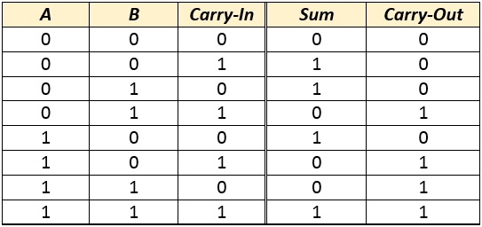 |
1 |Verify the simulation button if it is play or paused. Pause button indicates simulation is going on, while Play button signifies the simulation is paused.By default, the BOOLR app is always on simulation.

2 | Verifying our discussion earlier, input the values. Observe the result at the OUTPUT. To change the values of input, click on the number inside the input symbol.

3 | Change values of input to 1 and 1 respectively. Follow step 2 on how to change the input values.

Result of Simulation according to the truth table values.
       |
|---|
Curriculum
You can browse the other curriculum for BOOBLR Digital Logic Simulator.
Posted on Utopian.io - Rewarding Open Source Contributors
Hey @juecoree, your contribution was rejected by the supervisor @espoem because he found out that it did not follow the Utopian rules.
Upvote this comment to help Utopian grow its power and help other Open Source contributions like this one. Do you want to chat? Join me on Discord.
Thank you for the contribution. It has been approved.
You can contact us on Discord.
[utopian-moderator]
Thanks @kizilelma
You got a 2.24% upvote from @upmyvote courtesy of @juecoree!
If you believe this post is spam or abuse, please report it to our Discord #abuse channel.
If you want to support our Curation Digest or our Spam & Abuse prevention efforts, please vote @themarkymark as witness.
I'm not at all a hardware guy, but this is a nice piece of software to play with. Will definitely check it out, thanks for the post.
That would be great @laxam .
Hi, I am sorry to change the decision about this contribution but you did not plan the tutorial well. Some of the topics/circuits could be put together for better understanding.
Additionally, you repeat the part 1 in every post, include unnecessary images of states that are not that important for the tutorial. That makes your posts look longer but the actual information is more or less only in a half of the post.
It could be also said that the essential tutorial could be written in the first post of the series because that one could show how to use the program for digital logic. Talking about each circuit has its own value but it is not really specific to the software you used.
You can contact us on Discord.
[utopian-moderator]