Electronics Simulations #3| Constructing 7 Segment LED Display Decoder with SimulIDE
What Will I Learn?
In this tutorial, utopians :
- will get used to logic gates
- will have basic ideas about LED displays
- will be able to construct 7 segment LED display circuit with the help of SimulIDE software.

Requirements
To complete the tutorial, utopians would have:
- basic knowledge about digital circuits
- basic knowledge about LED displays
- SimulIDE circuit simulator software
Difficulty
- Intermediate
Tutorial Contents
In this tutorial, I will design a BCD to 7 Segment LED Display Decoder Circuit. Link for the circuit will be given in the credit parts at the end of the tutorial. To make simulations I will use SimulIDE software. 7 Segment LED Display circuit gives satisfying idea about the digital circuit environment. Those who studies on this circuit will have satisfied knowledge about digital circuit world.
- Episode 1: 7 segment IC
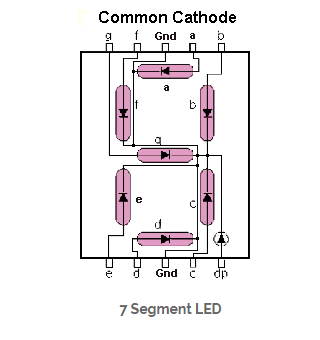
Source for the image
7-segment LED IC, allows to user to display digital data in the form of any alpha-numerical character.Basic idea of the circuit is given below:
The logic circuit is designed with 4 inputs and 7 outputs, each representing an input to the display IC. Using Karnough’s map, logic circuitry for each input to the display is designed.
- Episode 2: Constructing the circuit with the software
Circuit schematic is given below:
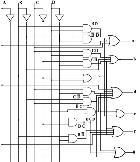
Source for the circuit
The circuit basically gives output for the given inputs, by comparing the input, each input of 7 segment LED will correspond to one part of the IC. You can give desired character by controlling the input voltages.
As a normal procedure, the circuit has been constructed with the help of Karnough map, truth table methods. For further information, reader should check the link which will be provided at source part.
To use 7 segment component in the software, one need to find 7 Segment component under "Outputs" part as shown below
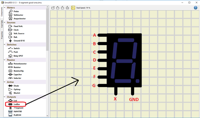
I have provide the corresponding inputs for this component. Input terminal X controls the small dot which is placed at right bottom of the component and will not be used for this project.
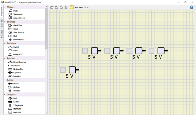
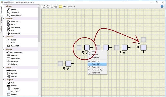
Next step is to construct the inputs and the corresponding gates. Firstly, lets put the inputs by using the Fixed Volt. under Sources part on the component window and put 5 of them. 4 of the sources will correspond the input, and the other one is to construct NOT gate.
If you want, you can change the directions of the components by right clicking them, and click the direction that you want.
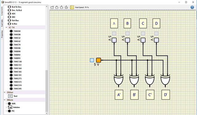
As explained in part 1 of tutorials, I designed NOT gate by using XOR gates. You can find the gates from Logic subtitle in the component parts.
Final structure for the inputs should look like:
All we need to do is just to connect corresponding gates with the given circuit. Final version of the circuit should look like:(Note that I have used multiple OR & AND gates in order to obtain 3 or 4 port gates,which is explained in part 1
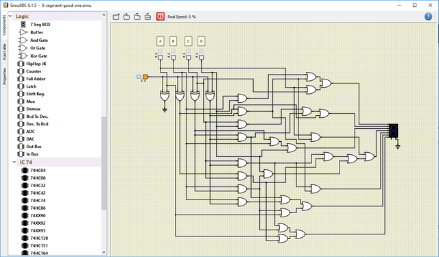
Final circuit should work like:
And finally I have uploaded my circuit as a .simu file which can be downloaded from here
Notice that I have not shared the code for the circuit,since it is already inside the .simu file (and also it was too long to state here) that I have uploaded for you, and on the next tutorials, I will explain how to take code from the given .simu file. If you have any questions, feel free to ask me on Discord (Escorn#4114)
Sources
Curriculum
I have provided the previous tutorials that I have prepared for the community:
Posted on Utopian.io - Rewarding Open Source Contributors
@escorn, I like your contribution to open source project, so I upvote to support you.
Thank you for the contribution. It has been approved.
You can contact us on Discord.
[utopian-moderator]
Hey @escorn I am @utopian-io. I have just upvoted you!
Achievements
Suggestions
Get Noticed!
Community-Driven Witness!
I am the first and only Steem Community-Driven Witness. Participate on Discord. Lets GROW TOGETHER!
Up-vote this comment to grow my power and help Open Source contributions like this one. Want to chat? Join me on Discord https://discord.gg/Pc8HG9x