Construction & Implementation of Demultiplexer by using "Digital" (step-by-step explanation)
What Will I Learn?
In this tutorial, readers:
- will learn basics of demultiplexers
- will learn the implementation demultiplexers
- will learn how to construct demultiplexer on "Digital"
Requirements
In order to complete the tutorial, readers would have:
- basic idea about logic gates, logic circuit environment
- a working PC
- "Digital" software
Difficulty
- Intermediate
Tutorial Contents
In this tutorial, I am going to show the basics & construction steps of demultiplexer digital circuits on the digital circuit simulator "Digital". Before construction of the circuit, I am going to explain demultiplexers in general ( such as working principle, reasons to use), and after the construction I am going to show simulation results at the end of the tutorial. Let me start with explaining demultiplexers.
- Episode 1: What is demultiplexer ?
Demultiplexer (Demux) is a data transfer circuit, which is widely used in digital circuit environment. It basically takes the input and transfers one of the outputs by the switch controls inside it.
Demultiplexers converts serial data to parallel data, to enlarge the operation wide of the circuit.
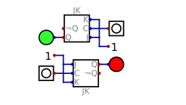
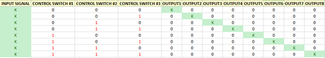
An example of input/output relation of a demux is given below (which is 8-to-1 demultiplexer):
From here, we can see that input K can be sent corresponding output by controlling control switches. ( K may be 0 or 1).
From now on control switches will called as, S2 S1 S0 from higher order to lower order and input will called as K We can express outputs such as:
OUTPUT1=KS2'S1'S0'
OUTPUT2=KS2'S1'S0
OUTPUT3=KS2'S1S0'
OUTPUT4=KS2'S1S0
OUTPUT5=KS2S1'S0'
OUTPUT6=KS2S1'S0
OUTPUT7=KS2S1S0'
OUTPUT8=KS2S1S0
(Note that ' corresponds to NOT operation)
So,we can construct the overall logic circuits by using NOT and AND(4input) gates
- Episode 2: Construction 8-to-1 demux on "Digital"
After this point, we are ready to construct our 8-to-1 demux circuit. I will construct the circuits step by step,
- Adding Inputs,
As a first step I will add inputs & label them as follows:
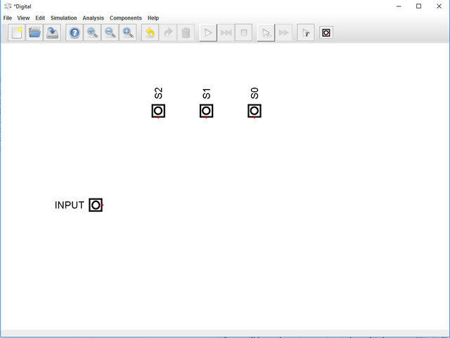
(Notice that I have labeled & rotated the corresponding gates by right clicking them)
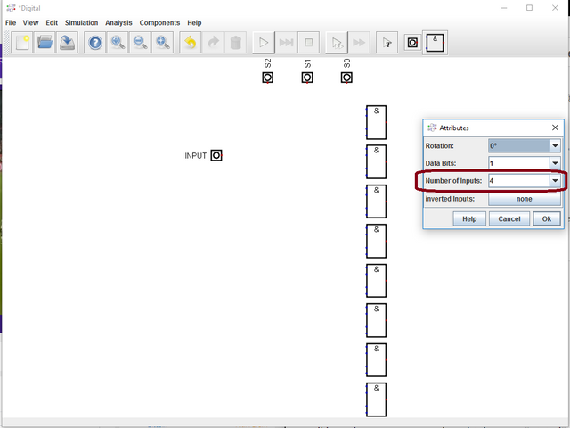
- Adding AND gates
As a second step I will add 8 (4-input) AND gates as following:
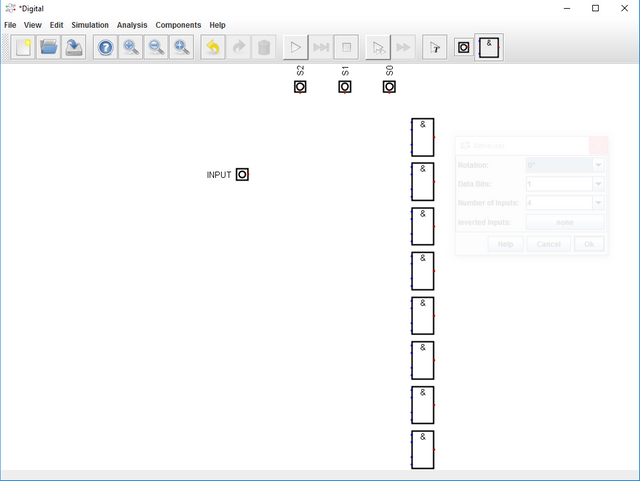
Note that I have changed the number of inputs on AND gates on Properties as:
- Adding NOT gates
As a third step, I will add NOT gates on Switches since we will need to use them.
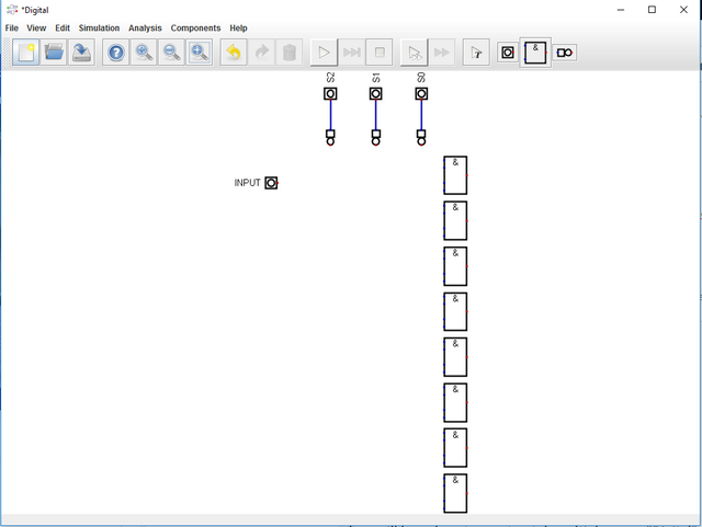
Now we have INPUT,S2,S1,S0,S2',S1',S0' (which is enough to construct demultiplexer)
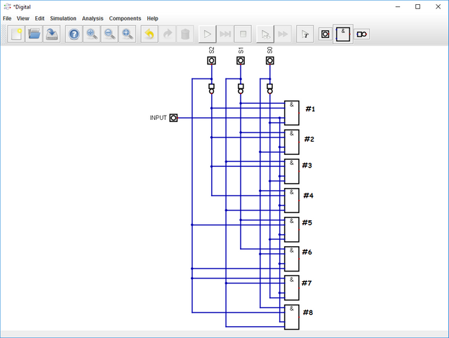
- Wiring Gates
As a fourth step, I will wire the inputs & outputs of the logic gates.Wiring operation as follows:
INPUT is connected to ALL gates.
S2 is connected to #5 #6 #7 #8 gates.
S1 is connected to #3 #4 #7 #8 gates.
S0 is connected to #2 #4 #6 #8 gates.
S2' is connected to #1 #2 #3 #4 gates.
S1' is connected to #1 #2 #5 #6 gates.
S0' is connected to #1 #3 #5 #7 gates.
- Adding LEDs
As a last step, to visualize the circuit, I have added LEDs for output of the ANDgates.
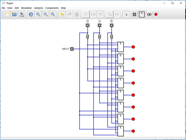
We have completed the construction.
- Episode 3: Simulation of the demultiplexer in "Digital"
In order to begin simulation, all we need to do is click Simulation button. The results are shown below:
I have provided the files for this tutorial here. I highly recommend that the reader should work on the files that I have provided and try to understand the basics of the circuit & software. It will be benefical for he/she.
This is the end for this tutorial.Hope that you like it.
Digital is a really effective and easy to learn software, I highly recommend this software for the one who wants to make simulation in digital circuits especially. If you have any questions, please feel free to ask me on Discord (Escorn#4114)
Curriculum
I have provided the previous tutorials that I have prepared for the community:
| SimulIDE | Caneda | Digital | LogiJS |
|---|---|---|---|
| Part 1 | Part 1 | Part 1 | Part 1 |
| Part 2 | Part 2 | Part 2 | |
| Part 3 | Part 3 | ||
| Part 4 | Part 4 | ||
| - | Part 5 | ||
| - | Part 6 | ||
| - | Part 7 |
Posted on Utopian.io - Rewarding Open Source Contributors
@escorn, I like your contribution to open source project, so I upvote to support you.
Thank you for the contribution. It has been approved.
You can contact us on Discord.
[utopian-moderator]
Hey @escorn I am @utopian-io. I have just upvoted you!
Achievements
Suggestions
Get Noticed!
Community-Driven Witness!
I am the first and only Steem Community-Driven Witness. Participate on Discord. Lets GROW TOGETHER!
Up-vote this comment to grow my power and help Open Source contributions like this one. Want to chat? Join me on Discord https://discord.gg/Pc8HG9x
Hmmm... I like your post, but I'd use ANSI logic function symbols as for me those are more readable and more commonly used.
Still - very good post. Keep up the work.
I am very glad that you liked it. Symbols are helded by the software
Oh, so the software uses those symbols. That explains it.