DESIGN AND CONSTRUCTION OF A 1KVA FUELLESS GENERATOR.

ABSTRACT
Today Nigeria faces a destabilizing dependency on irreplaceable fossil fuels which are also rapidly dwindling. As shortages of oil and natural gas occur with more frequency, the “New Energy Crisis” is now heralded in the news media. However, an alternate source of energy that can replace fossil fuels has not been reliably demonstrated. A real need exists for a portable source of power that can compete with fossil fuel and its energy density. A further need exists on land, in the air, and in space, for a fuelless source of power which, by definition, does not require re-fuelling. The future freedom, and quite possibly the future survival, of mankind depend on the utilization of such a source of energy, if it exists
Therefore, in order to find other ways of producing energy, a number of alternatives have been considered. One of these alternatives is the generation of electricity from a fuelless engine in an isolated power generation system with low maintenance cost. Electricity supply has been erratic for a long while in Nigeria. The need for new energy sources had led to a number of alternatives, which have been unaffordable and unavailable due to huge cost and scarcity. In response to this, fuelless generator was designed and developed using local materials. The driving mechanism of fuelless generator is the 3hp direct current motor, powered by a 12 volts 62Ah battery, which spines the 0.95KW alternator to produce electricity, while recharging the battery by means of a solar energy. The fuelless generator has an output of 1KVA; it is pollution-free and eco-friendly.
CHAPTER ONE
INTRODUCTION
Background to the study
The global consumption of energy is growing and there is need for new renewable energy sources. Among the following energy sources that could be free from carbon dioxide are wind, wave and tidal of photovoltaic and osmotic power. But fuelless engine is still most dependable low maintenance cost energy new renewable solutions. The use of low cost, conventional energy such as fossil fuels will continue to be major source of energy until next decades, despite their adverse effect on environment. The pressure on the environment by human activities compiled with carbon dioxide emissions calls for thorough research on the alternatives.
Now a new principle can be applied to electricity generation leading to electricity cycle, bringing electricity revolution in Nigeria. Ordinarily conventional electricity generators make use of fuel or solar/wind or nuclear energy etc. In the case of fuel (in this analysis fuel can be petrol, diesel, steam, charcoal, kerosene etc.), an internal combustion engine is involved. This engine uses the chemical energy in the fuel converts it into mechanical energy that will be used to drive the alternator thereby generating electricity based on the principle of electromagnetic induction.
Today Nigeria faces a destabilizing dependency on irreplaceable fossil fuels which are also rapidly dwindling. As shortages of oil and natural gas occur with more frequency, the “New Energy Crisis” is now heralded in the news media. However, an alternative source of energy that can replace fossil fuels has not been reliable demonstrated. A real need exists for portable source of power that can compete with fossil fuel and its energy density. A further need exists on land, in air, and in space, for a fuel-less source of power which, by definition, does not require re-fueling. The future freedom, and quite possibly the future survival, of mankind depend on the utilization of such a source of energy, if it exists.
A fuel-less engine is an engine that produces electricity 24/7 without fuel (petrol, diesel, oil, grease, gas, wind energy). Fuel-less engine can replace any of these engines types. Fuel-less engine has very little impact on the environment, noiseless, pollution free, self-dependent. It can be built to the capacity of the load you want it to carry. The driving mechanism is the DC motor, which is driven by a battery (12V or more). The battery drives the DC motor, which in turn spins the alternator to produce electricity and at the same time, with the help of the solar energy, it recharges back the battery. It requires a suitable controller to regulate the voltage due to variation of consumer loads. There are several different types of engine and all have different uses on the road, in the air, on the water, under the ground, in the hospitals and behind the data centers.
Statement of Problem
The Engineering challenge of generating energy from a fuel-less generator or engine for useful work is, at the turn of this century, plagued by ignorance, prejudice and disbelief. The power engineers’ community does not in general acknowledge the emerging opportunities from fundamental discoveries of fuelless energy. Instead, there are many expositions from prominent sources against it.
There is no functional fuel-less generator in the laboratories in many Engineering schools in Nigeria, even in EEE department of Univ0ersity of Uyo.
With convincing skeptical arguments like these from the experts, how can a generator work without any fossil fuel and have good performance like fuel-generator? What engineering protocol can be theoretically developed for the designing of a fuel-less generator if it can be reasonably considered to be feasible? These are the central problems that are addressed by our thesis.
Aims and objectives the study
The aim of this study is to design and fabricate a 1KVA fuel-less generator that is efficient and less energy consuming. Its specific objectives are:
Provide an alternative to fuel generator which is not environmental friendly.
Come up with a finalized design.
To design a portable fuel-less generator that can be very affordable.
To determine the efficiency of the designed generator
To analyze the input and output characteristics of the designed generator.
1.3 Scope/Limitation of the project
The project covers the design and fabrication of a 1 KVA fuel-less generator. The availability and the cost of the raw materials needed for this fabrication will pose as a major challenge. The raw materials required for the fabrication will be sourced for locally. The limitation of this project is that the design and construction of this generator is limited to a maximum output 1KVA of electric power. This means that the generator can only be put to use in areas that do not demand more than 1KVA of power.
1.4 Methodology
In designing and fabricating of this fuel-less generator, a flow of methods had to be used, in the design of this fuelless generator. First of all, a process planning had to be charted out. This acts as a guideline to be followed so that, the final model meets the requirement and time could be managed. This would determine the efficiency of the project to be done. Regulating and analyzing these steps are very important as each of it has its own criteria to be followed. We will adopt following stages:
Surfing the net for information.
Collecting literature.
Market survey.
Analysis of the model designed.
Modeling using computer aided software (Auto CAD).
Fabrication
Testing the fabricated machine.
CHAPTER TWO
LITERATURE REVIEW
2.1 Introduction
This chapter aims at reviewing relevant literature on the topic. Under this chapter, terms such as history of generators will first be conceptualized follow by early developments of fuelless generator and recent developments of fuelless generator. Similarly, this chapter will also focus on empirical review studies on the benefits of electricity, the erratic power supply nature experience in Nigeria, effects and environmental pollution caused by the use of fuel generators. Lastly, the driving mechanism of the fuelless generator, the working principle and the controlling method of the fuelless generator.
2.2 History of Generators
Before the connection between magnetism and electricity was discovered, electrostatic generators were used. They operated on electrostatic principles. Such generators generated very high voltage and low current. They operated by using moving electrically charged belts, plates, and disks that carried charge to a high potential electrode. The charge was generated using either of two mechanisms: Electrostatic induction and the triboelectric effect. Because of their inefficiency and the difficulty of insulating machines that produced very high voltages, electrostatic generators had low power ratings, and were never used for generation of commercially significant quantities of electric power. (Thomas, John Meurig (1991). Michael Faraday and the Royal Institution: The Genius of Man and Place. Bristol: Hilger.p.51.ISBN0750301457.)
[1/16, 12:54 AM] Spiritwalker: The Faraday disk was the first electric generator. The horseshoe-shaped magnet (A) created a magnetic field through the disk (D). When the disk was turned, this induced an electric current radially outward from the centre toward the rim. The current flowed out through the sliding spring contact m, through the external circuit, and back into the center of the disk through the axle.
2.2.1 Electromagnetism:
The operating principle of electromagnetic generators was discovered in the years of 1831–1832 by Michael Faraday. The principle, later called Faraday's law, is that an Electromotive force is generated in an electrical conductor which encircles a varying Magnetic flux. He also built the first electromagnetic generator, called the Faraday disk, a type of homopolar generator, using a copper disc rotating between the poles of a horseshoe magnet. It produced a small DC voltage. This design was inefficient, due to self-cancelling counter flows of current in regions that were not under the influence of the magnetic field. While current was induced directly underneath the magnet, the current would circulate backwards in regions that were outside the influence of the magnetic field. This counter flow limited the power output to the pickup wires, and induced waste heating of the copper disc. Later homopolar generators would solve this problem by using an array of magnets arranged around the disc perimeter to maintain a steady field effect in one current-flow direction. Another disadvantage was that the output voltage was very low, due to the single current path through the magnetic flux. (Losty, H.H.W & Lewis, D.L. (1973) Homopolar Machines. Philosophical Transactions for the Royal Society of London. Series A, Mathematical and Physical Sciences. 275 (1248), PP.69-75)
Experimenters found that using multiple turns of wire in a coil could produce higher, more useful voltages. Since the output voltage is proportional to the number of turns, generators could be easily designed to produce any desired voltage by varying the number of turns. Wire windings became a basic feature of all subsequent generator designs. Independently of Faraday, the Hungarian AnyosJedlik started experimenting in 1827 with the electromagnetic rotating devices which he called electromagnetic self-rotors. In the prototype of the single-pole electric starter (finished between 1852 and 1854) both the stationary and the revolving parts were electromagnetic. He also may have formulated the concept of the dynamo in 1861 (before Siemens and Wheatstone) but didn't patent it as he thought he wasn't the first to realize this.
(Beauchamp, K G (1997).“Exhibiting Electricity”.IET.p.90. ISBN 9780852968956.)
2.2.2 Direct current generators
2.2.2.1 Evolution of Dynamos:
[1/16, 12:56 AM] Spiritwalker: he dynamo was the first electrical generator capable of delivering power for industry. The dynamo uses electromagnetic induction to convert mechanical rotation into direct current through the use of a commutator. An early dynamo was built by Hippolyte Pixii in 1832. The modern dynamo, fit for use in industrial applications, was invented independently by Sir Charles Wheatstone, Werner von Siemens and Samuel Alfred Varley. Varley took out a patent on 24 December 1866, while Siemens and Wheatstone both announced their discoveries on 17 January 1867, the latter delivering a paper on his discovery to the Royal Society. The "dynamo-electric machine" employed self-powering electromagnetic field coils rather than permanent magnets to create the stator field. Whetstone’s design was similar to Siemens', with the difference that in the Siemens design the stator electromagnets were in series with the rotor, but in Whetstone’s design they were in parallel. The use of electromagnets rather than permanent magnets greatly increased the power output of a dynamo and enabled high power generation for the first time. This invention led directly to the first major industrial uses of electricity. For example, in the 1870s Siemens used electromagnetic dynamos to power electric arc furnaces for the production of metals and other materials. (Thompson, Sylvanus P., “Dynamo-Electric Machinery”. p. 7)
The dynamo machine that was developed consisted of a stationary structure, which provides the magnetic field, and a set of rotating windings which turn within that field. On larger machines the constant magnetic field is provided by one or more electromagnets, which are usually called field coils. Dynamos are no longer used due to the size and complexity of the commutator needed for high power applications. Large power generation dynamos are now rarely seen due to the now nearly universal use of alternating current for power distribution. Before the adoption of AC, very large direct-current dynamos were the only means of power generation and distribution. AC has come to dominate due to the ability of AC to be easily transformed to and from very high voltages to permit low losses over large distances. (Thompson, Sylvanus P., Dynamo-Electric Machinery. pp. 16-17)
2.2.3 Alternating current generators
[1/16, 12:57 AM] Spiritwalker: Through a series of discoveries, the dynamo was succeeded by many later inventions, especially the AC alternator, which was capable of generating alternating current. Alternating current generating systems were known in simple forms from Michael Faraday’s original discovery of the magnetic induction of electric current. Faraday himself built an early alternator. His machine was a "rotating rectangle", whose operation was heteropolar - each active conductor passed successively through regions where the magnetic field was in opposite directions. Large two-phase alternating current generators were built by a British electrician, J.E.H. Gordon, in 1882. The first public demonstration of an "alternator system" was given by William Stanley, Jr., an employee of Westinghouse Electric in 1886. Sebastian Zianide Ferranti established Ferranti, Thompson and Ince in 1882, to market his Ferranti-Thompson Alternator, invented with the help of renowned physicist Lord Kelvin. His early alternators produced frequencies between 100 and 300 Hz. Ferranti went on to design the Deptford Power Station for the London Electric Supply Corporation in 1887 using an alternating current system. On its completion in 1891, it was the first truly modern power station, supplying high-voltage AC power that was then "stepped down" for consumer use on each street. This basic system remains in use today around the world.
(Blalock, Thomas J., "Alternating Current Electrification, 1886 ". IEEE History Center, IEEE Milestone.)
After 1891, polyphase alternators were introduced to supply currents of multiple differing phases. Later alternators were designed for varying alternating-current frequencies between sixteen and about one hundred hertz, for use with arc lighting, incandescent lighting and electric motors.
(YoshihideHase, "10: Theory of generators", Handbook of Power System Engineering, John Wiley & Sons, 2007 ISBN 0470033665.)
2.3 Early Developments of Fuel-less Generator
First envisioned by Nikola Tesla in the early years of the 20th century, the fuelless engine is a device that is understood to function without the need for a wired power source. Even so, the concept of a mass produced fuel-less engine has remained an interesting proposition to engineers today. Many papers have been written on the feasibility of building such an engine based on the work of Tesla. At conferences and trade shows, it is not unusual to find engineers who speak in support of the idea of Tesla’s fuelless engine from time to time, small scale models were constructed. However, it does not appear to be at this working prototype that can be produced for use in industry or by the general populace.
2.4 Recent Developments of Fuel-less Generator
The newest and most promising renewable energy technology competing with self-charging competing with self-charging inverters is the fuel-less engine though costlier than the latter. The self-charging inverters could be in modules of 5000 watts while fuel-less engine could be designed and constructed to the two-thirds of the 500hp (373kw) capacity of the DC motor that drives the alternator thereby producing 333hp (248.7kw) output.
It was observed that the output remains constant irrespective of the number of the batteries used starting from 1 or 2 batteries in series to produce 24v that drives the dc motor although using 2 number of 200AH deep cycle batteries drives the DC motor faster than using 2 number of 100AH deep cycle batteries. Once the rate of discharging the batteries is equal to the rate of charging the batteries then the output voltage remains constant and the fuelless engine could operate 365 days without any interruption. This is an ideal renewable energy source. The source of energy comes from within the realm of physics but there is an opposing challenge to the 1st law of thermodynamics which is generally referred to as principle or law of conservation of energy. The technique to generate electricity out of this fuelless engine has been tested and proved reliable and steady.
Empirical Review
The exert nature of electricity is not known but investigation indicate that it consist of small negative charge called Electron, when this electron are standing still we have static electricity” and when they are forced to traveled a movement of electron they are called “Dynamic electricity.” Power generation and distribution has been an indispensable factor in the progress of an economy, ranging from manufacturing, banking, media, health care, aviation, etc. (Ulaby, 1999). It has however been proved that power skyrocket the productivity of a country. Since power has been defined by Knight (2004) as the rate of doing work; this simply means that the productivity of a country will largely depend on the availability of power from different source.
Thus, Hassen (1989) cited in Ulaby (1999) states that majority of the problems of Nigeria is traceable to the erratic power supply nature of the country, where many activities has been paralyzed due to the power outage. Analysis has clearly showed that Nigeria lose up to about N220 Billion annually, due to the unstable nature of the country power supply which has poses a threat, hence reducing the capacity of industries to increase productivity (James, 2005).Environmental pollution which leads to degradation or depletion of ozone layer is one of the major problems caused by the use of generator with fossil fuels (Ajav, 2012). Other problem includes land and water pollution, noise pollution, increase in price of fossil fuel year in year out, among others. The famous Faraday energy generator can be modified for perpetual electrical current maintenance (Adiyat et.al, 1993). The basic components the fuelless engines consisted of are a set of fast spinning discs placed between two electromagnets. But this scheme could never maintain current indefinitely, because the disc electrical charge is weak to withstand the opposing resistance of the conductor. Practically, the effective working fuelless generator have to be built by each material that have one thousand times the electrical conductivity of copper could generate and maintain self-sustained current. It is suggested that increasing disc rotation to incomprehensible velocity or huge component geometrical enlargements would have the same effect too (Taufik, 2005). It is necessary to spin discs with the super-rapidity required to generate self-sustaining electrical current.
The fuelless engine usually runs very smooth and quiet and the best part of the design is that it is free from air pollution, since there is no emission of dangerous gas like Carbon monoxide (CO), carbon-dioxide (CO2)
The speed is adjustable or can be built to run a tone speed with engine which does not run on any type of gasoline, oil or other combustible fuel. The free electrical energy produced by the fuelless generators is replaced back into the motor and reused by the motor (Maini, 1998). Heavy electrical machinery that starts automatically or remotely generally makes use of contactors which rely on an electromagnetic force to close them to start the machinery. This force is created by an electric coil placed in the center of a laminated steel core. These coils are typically designed to operate at fairly low voltages, ranging from 110 volts to as low as 12 volts. As these machines themselves typically run on far higher voltages, this creates the need for a separate control voltage feed. Instead of having to run separate cables or install extra sets of bus bars, it is far simpler to use the main circuit voltage and step it down with a control transformer to the appropriate control voltage (Wisegeek, 2013).
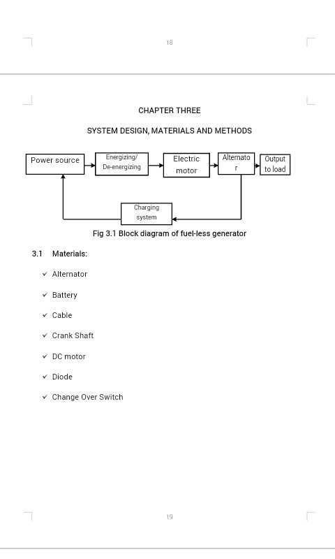
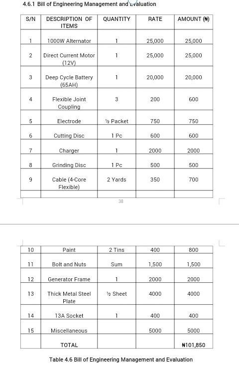
3.3 Fuel-less Power Generating Set Components Units
The fuel-less power generating set consists of five major units, which includes the following;
The power supply Unit.
Conversion Unit.
Control Unit.
Output Unit.
Charging Unit
3.3.1 The Power Supply Unit
12 volts battery was used as source of power supply unit to the D.C motor in order to induce electromotive force (e.m.f). Lead acid battery is highly recommended for DC generating system. This serves as storage device for the direct current which is to be induced
3.3.2 Conversion Unit
This unit is the unit that distinguished the DC generator from the popular fuelled generating set. The unit makes use of DC motor, which will be responsible for all voltage, current and power conversion.
3.3.3 Control Unit
This unit performs the following work; converts direct current (DC) to alternating current (AC), removal of ripples, and rectification. The size of the alternator been used, will determine the capacity of the generating set.
Mathematically; P = IV cos Ф (i)
Where
P = Power output (watts) =?
V = Voltage (Volts) = 220
I = Current (ampere) = 5.35A
Cos Ф = 0.85
Therefore, the capacity of the generating set,
P = 5.35 x 220 x 0.85 = 1000W
The alternator which is a small domestic generator has three output lead cables which supplies, the load, capacitor and the diode.
Crank Shaft
The crankshaft acts as a link between the DC motor and the alternator which transfer the mechanical energy from the DC motor into the alternator to produce electric current. See appendix for calculation on shaft diameter selection.
3.3.5 Output Unit
The use of the control circuit unit will make it possible to provide output voltage within the range of 100V - 240V which is the standard voltage requirement for all appliances. The red wire on the alternator was used to supply the household and offices as the mains.
3.4 Constructional Features
The constructional features are as discussed below:
3.4.1 The Frame
This part provides support to all components of the fuelless generator. It serves as housing for all component parts of the machine. A piece of angle iron 40mm x 40mm x 5mmwas measured, cut to sizes and welded together to make a stand of length 61mm, width40mm and height 19mm; brazed at different points for regularity with angle bar of 1.5mm x1.5mm
3.4.2 The Motor Seat
A piece of angle iron of dimension mentioned for the frame was cut into length 21mm x10mm and which was welded to the main frame as shown
3.4.3 Alternator Seat
A piece of angle iron of above dimension (1.5mm x 1.5mm) from the frame was cut into length 20.5mm x 12mm and was welded to the frame.
3.4.4 Battery and Charging Panel Seat
The plate was measured and cut into the length of 60mm x 19mm and welded to the frame to make up with the seat of battery and the self-charging panel of the generating set.
3.4.5 Alternator
A permanent magnet alternator is a power generating device that produces a sinusoidal output when a mechanical input to its hub or shaft is applied. This device is constructed very much like a brushless motor with the appropriate selection of insulation materials and winding to match the environment and application. Alternator used for this research work has the following nominal parameters as specifications;
Voltage = 12V
Current = 5.3 A
Speed = 6000rpm
Minimum speed for accumulator charging initiation = 1300rpm.
They are produced in a variety of power and voltage levels and generally are always examined from many points of view, such as reliability, efficiency, dimensions weight and costs.
3.4.6 D.C Motor
Electric motors are electric generators reversed in function. They convert electrical energy into mechanical energy- the continual stresses between two electromagnetic field relatively moveable, just as generator convert into electromagnetic stresses, the mechanical energy applied to them (Aremu, 2009). Power from the electric motor is transmitted into the alternator via rotating shaft driven system. Electric motor used for this research work has the following configuration; 9000rpm (Speed), 12V.
3.5 Construction/Design Procedures
In the design of the fuel-less generating set, the following procedural steps are used to achieve the aims and objectives of the construction work.
Step 1: Fabricated crankshaft with a bore-hole that conveniently fit in to the DC motor with thread-hole that bolt the motor to the crankshaft.
Step 2: Fitted the fabricated crankshaft in to the DC motor
Step 3: Inserted the DC motor with crankshaft into the crank casing of the alternator.
Step 4: Fit the armature of the alternator into the casing.
Step 5: Dropping the stator core of the alternator into the armature
Step 6: Inserted a long bolt through the bearing end of the stator and tighten firmly to connect the motor and the alternator together.
Step 7: Replaced the cover of the alternator and fasten both the cover and the crankcase together.
Step 8: Constructed a frame for the generator to provide support and rigidity
Step 9: Connected the diode to green cables and capacitor to the yellow ones.
Step 10: Connected the terminals of the DC motor to equivalent terminals of the battery
Step 11: Connected the red cables to the mains as output.
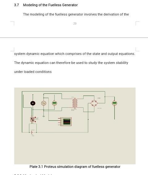
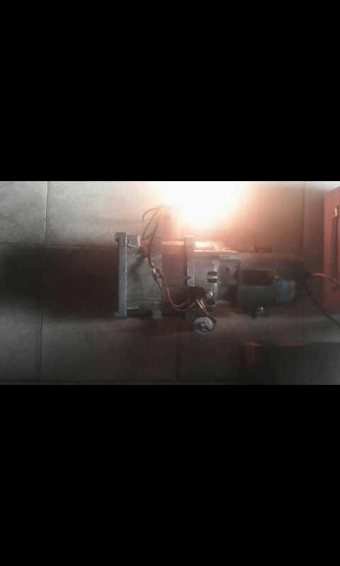
3.6 Fuelless Engine Process
Below is the description of fuelless engine. The cranked shaft is tighten to the DC motor , The DC motor, which is an electric motor that runs on direct current, is coupled to the alternator case using hex bolts of 5mm. The channel, which is a base, is constructed with metals by a welder and it houses the DC motor and the alternator. 12V, 65AH deep cycle batteries are connected with 4mm insulated copper wires in series (to give 24V) to a switch that is off and from the switch to the DC motor. The insulated wires are used to connect the alternator AC output to both the load and 24V, 60A charger. The charger provides constant recharging of the batteries as the DC motor consumes energy from the batteries. The positive and negative terminals of the charger are connected to the positive and negative terminals of the batteries respectively with the switch on, the batteries turn the DC motor, the DC motor drives the alternator and the alternator produces electricity having voltage up to 240V and carries the load while charging the batteries at the same time with the help of the electricity also supplied to the charger. The voltage meter shows a constant value of 240V for as long as the switch is on. The alternator has diode that gives polarity (+Ve and –Ve) to the batteries and capacitor that stores electrical charges smoothen the electricity supplied by the alternator. 
3.6.1 Mechanical Model:
Let the mechanical model comprise of the rotating parts (i.e. armature winding of the motor and the rotor winding of the alternator) which are function of speed
Then,
Te ═ TL J – Bωm (ii)
Where,
Te ═ Electromagnetic torque (NM)
J ═ Moment of Inertia (KG/M2)
TL ═ Load torque (NM)
B ═ Viscous friction confident
ωm ═ mechanical speed (rad/sec)
If the load torque is neglected, then from the above equation, we have
Te = -jdω m -Bωm (iii)
═ -Te - Bωm
But Te═ kbIa
Thus, ═ Ia – ωm (iv)
II. Electrical Model
Let Vf ═RfIf + L + e (v)
Where,
e ═ Kbωm ═ induced emf
Vf ═ field voltage
If ═ field current and
L ═ field inductance
Then, ═ - if - ωm
═ -if - ωm+ Vf (vi)
if if ═ ia ═ i, then equation (iv) and (vi) becomes
═ iωm (vii)
═ -iωm + V (viii)
CHAPTER FOUR
PERFORMANCE EVALUATION
4.1 Introduction
This evaluation is intended to establish the conversion efficiency between the fuelless dc source (PV) input and the ac output. This will include response to variations in input power, input and output voltage, ambient temperature as revealed by Sandia (2004) according to IEEE standard. In all cases of the following tests, the ac output was measured on the utility side. In this test, the generator efficiency is characterized as a function of array power, array voltage, utility voltage, and ambient temperature.
4.2 TESTING
In order to ascertain the workability, reliability, and operating characteristics of the fuelless generator, tests were carried out severally on both unloaded and loaded conditions. The results of these tests were then use to validate the fuel-less generator with the already existing ones.
Also tests were carried out on the individual components that make up the fuelless generator in order to know their behaviour under working condition.
4.3 Output Efficiency for fuelless Power Generator
Table 1, Table 2, Table 3 and Table 4 in Appendix shows the result of performance evaluation for the 1000W (1KVA) fuelless power generating set. The load bank was connected to the fuelless generator in order to power the light bulbs on the bank, which was connected to the extension wire. Stop watch was used to record the time at interval of 60 seconds for five different runs. While the multi-meter was used to read the voltage output in Volts with Current in Ampere and the mean voltage with current result was computed in the Table 1, Table 2, Table 3 and Table 4 in the Appendix page.
Output efficiency was computed using the data obtained after testing, according to Institute of Electrical and Electronics Engineers (IEEE, 1997) reported by Sandia Inverter (2004) as shown in the Appendix Table 1, Table 2, Table 3 and Table 4. Load capacity used for this research work ranges from 0 watt to1000 watts; that is from 0% to 100% loading. The speed of the motor used was 3000rpmwhile that of the alternator was 6000rpm. This simply means that there is direct coupling of the motor and the alternator since the speed is in ratio 1.5: 1. The power factor was kept constant (Ф = 0.85), since the standard range from IEEE is between 1 – 0.7 and local load bank was used in testing the machine which consist of light bulbs. Each test was replicated five times. The Institute of Electrical and Electronics Engineers (IEEE, 1997) cited by Abass (2013) was used as basis for comparison for a fuelless power generator and Inverter System
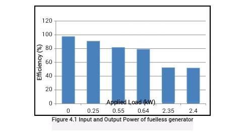
From the above chart, it is observed that as the voltage reduces while the current increase. This result support Ohm’s law finding that states that, the higher the voltage in the circuit, the higher the current.
4.4 Exploitation Possibilities
There are many possible ways to exploit the energy from fuelless engine when fully operated. With each of the possibilities, it seems the fuelless engine will be very useful and dependable. Below are brief descriptions of some of the possible approaches:
On Road
The fuelless engine can replace the diesel engines used in the vast majority of modern heavy road vehicles such as trucks, buses, long distance trains, large scale portable power engines and most farm and mining vehicles.
B. In Air
Both the petrol and diesel engines used in air planes can be replaced with fuelless engines.
C. On Water
Fuelless engines can replace the high speed engines that are used to power yachts, ships and lines along the high seas.
D. Under Ground
Fuelless engines can also replace diesel powered engines that are used by mining and mineral extraction sector worldwide to harness natural resources such as aggregate precious metals, iron ore, coal and oil gas.
E. In Hospitals:
Fuelless engines can replace emergency backup generators that must be made available for any major medical health care facilities due to critical nature of work
F. Behind Data Centres:
Fuelless engines can be used to power computers, the heart of today’s industry. When servers and systems go down, communication can be lost, business stops, data is lost, workers sit idle and just about everything comes to a halt.
4.5 D.C Motor Developments
The output capacity of the fuelless engine is determined mainly by output capacity of the dc motor. The dc motor capacity must exceed that of the alternator coupled to the dc motor in order to produce maximum alternator output capacity. Many dc motors of different output capacities are on sale throughout the world markets from 2hp (1.5kwatts) to 500hp (373kwatts). The development of the dc motor has been on for more than a century since these dc motors of smaller capacities are used in cars, tape recorders, pump machines, fans, winders, etc. The ultimate focus is to couple dc motor whose output capacity is more than that of alternator in order to drive the alternator maximally
4.6 Potentials of Fuelless Engine
The application of fuelless engine to generate electricity is restricted to capacity of both the D.C. motor and the alternator. This implies that the availability of D.C motor and alternator of large capacity gives the fuelless engine its potentials. Research has shown that the potential for fuelless engine globally is more than five times the potential of wind and solar for the fact that it works 24/7 on daily basis in any part of the world. Several D.C motor manufacturers throughout the World
CHAPTER FIVE
CONCLUSION AND RECOMMENDATIONS
5.1 Future Prospects of Fuelless Generator
When D.C motors of higher capacity than 500hp are coupled to the alternator whose capacities are lower than that of the D.C motors, then maximal output capacity of the alternator could be obtained. Fuelless engines can be incorporated into automobiles in order to have fuelless automobiles that would run without fuel
5.2 Conclusion
The need for new energy sources had led to a number of alternatives with their attendant teething high cost problems. However, in the future, if the technology is further developed and embraced the costs will reduce to compete reasonably with those of generators. Fuelless engine is a renewable energy source with insignificant or no CO2 emissions when sparking occur at the batteries terminals as a result of partial contact when wiring. Mostly, the fuelless engine potentials can be utilized by merely replacing all the generating sets electric or fuel powered motors, with dc motors and adequate chargers.
The following conclusions were drawn from the design, construction and performance evaluation of 1000W (1KVA) fuelless power generating set;
It can be deduced that the machine (fuelless power generating set) had the peak efficiency of 89.1% at a load of 100W and the lowest efficiency of 56.4% at a load of600W with voltage output of 131V.
It was also revealed that there is a decrease in the output of the machine when there is a high increase in the load.
After proper statistical analysis, the machine is said to have an average efficiency of 56.4%.
The input voltage which is usually supplied by the battery ranges from 11.68V at load of 1000W to 12.67 at 0W for fuelless power generating set compare to 10.3V at load of 1000W to 12.63V for power inverter.
This can be accounted for due to the fact that fuelless generating set has self charging component while the inverter system depends on main source (PHCN or Power Generating Set) for recharging the battery.
Furthermore, the voltage output in the power inverter system is more stable than that of fuelless power generating set as inverter system records output voltage which ranges between 146.8V at 1000W and 241.8V at 0W against the fuelless generating set that recorded 28.24V at 1000W to 225V at 0W respectively.
5.3 Recommendations
Based on the design, construction and performance evaluation test conducted on this1KVA fuelless power generating set, the following recommendations were made for further study;
In order to obtain a good performance characteristic, a voltage well above 12V battery voltage should be used to power the power generator
Design of special DC motor, alternator and transformer for the purpose of construction of fuelless power generating set has to be encouraged by engineers in society in order to have clean and renewable energy especially for solving the epileptic power supply been experienced in Nigeria currently.
The appliance can be adopted and made available for use in Electrical and Power establishments.
Test the efficiency of the project in terms of the accuracy of the output voltage, reliability of the output, safety, life span of the project and other parameters as suggested by the standard body for a standard portable generator.
Further improvement must be made in producing higher capacity of the fuelless generating set, in order to solve problem of the generation and distribution of electricity that is usually inadequate experiencing here in our country Nigeria.
And finally, we recommend this project work for further research to improve in the limitation..
Thanks for reading. This was a project originally done by my friend and I got his concert to share it with the world
his name and number
The design and construction of a 1KVA fuelless generator is an innovative and environmentally friendly solution that offers reliable power generation without the need for traditional fuel sources. For professional design and construction services related to billboards, signage, banners, yard signs, and signboards, visit https://www.fiverr.com/shoaibmaroof4/design-billboard-signage-banner-yard-sign-and-signboard. This groundbreaking technology provides a sustainable and cost-effective alternative to electricity generation. With its unique design and cutting-edge engineering, this fuelless generator harnesses renewable energy to produce clean and efficient power.